Diyinhk DXIO MC (3W)
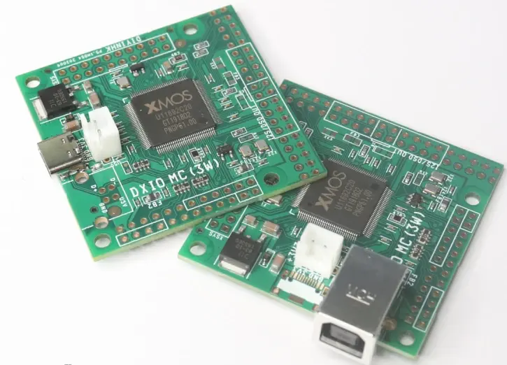
The first board used in the fuegocable XMOS firmware. It is based on the XMOS XUF216 chip, providing good processing power since it is internally based on two XU208 cores. This model has internal flash memory for firmware storage.
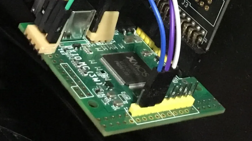
This board is especially useful because it has a header for connecting an XMOS XTAG 3 debug adapter, which makes firmware development and debugging easier.
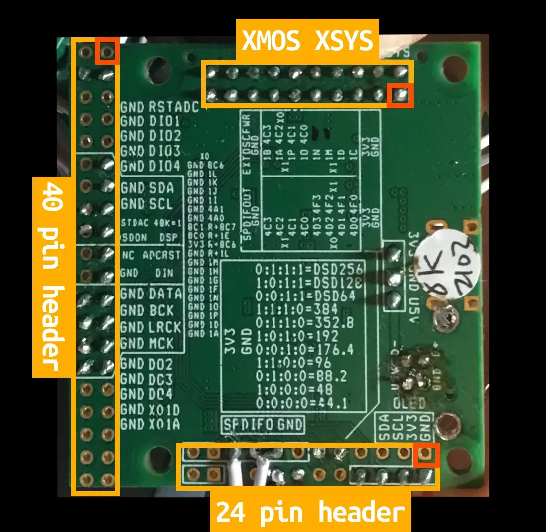
Each port exposed on a pin of the PCB headers is identified in the silkscreen on the bottom of the PCB. This can be somewhat confusing at first, so the following image aims to clarify the board's pinout.
Buyer link: https://www.diyinhk.com/shop/audio-kits/175-xmos-multichannel-high-quality-usb-tofrom-i2sdsd-spdif-pcb.html
(there is no commercial agreement with the manufacturer)
Currently, the XMOS hardware description for this board, present in the .xn file of the fuegocable firmware dxio_mc_3w.xn, defines specific roles for each bit of the available ports according to certain communication buses. This will probably change in the future, because in order for the fuegocable firmware to support multiple boards and their different hardware definitions, it would be preferable to define intermediate constants to configure the hardware for each audio interface in the most flexible and clear way possible.
Pinout
40-pin header pinout
| XMOS Pin name * | PCB XMOS Port Ref | PCB Ref | Pin N° | Pin N° | PCB Ref | PCB XMOS Port Ref | XMOS Pin name * |
|---|---|---|---|---|---|---|---|
| X0D32 | X0 8C6 | RST_ADC | 1 | 2 | GND | - | - |
| X0D35 | X0 1L | DIO1 | 3 | 4 | GND | - | - |
| X0D34 | X0 1K | DIO2 | 5 | 6 | GND | - | - |
| X0D25 | X0 1J | DIO3 | 7 | 8 | GND | - | - |
| X0D24 | X0 1I | DIO4 | 9 | 10 | GND | - | - |
| X0D03 | X0 4A1 | SDA | 11 | 12 | GND | - | - |
| X0D02 | X0 4A0 | SCL | 13 | 14 | GND | - | - |
| X0D33 | X0 8C7 (R) | 48K=1 | 15 | 16 | RSTDAC | X0 8C1 | X0D27 |
| X0D12 | X0 1E (R) | DSP | 17 | 18 | DSDON | X0 8C0 | X0D26 |
| X0D32 | X0 8C6 (R) | ADCRST | 19 | 20 | NC (3.3V) | - | - |
| X0D35 | X0 1L (R) | DIN | 21 | 22 | GND | - | - |
| X0D36 | X0 1M | DATA | 23 | 24 | GND | - | - |
| X0D23 | X0 1H | BCK | 25 | 26 | GND | - | - |
| X0D22 | X0 1G | LRCK | 27 | 28 | GND | - | - |
| X0D13 | X0 1F | MCK | 29 | 30 | GND | - | - |
| X0D37 | X0 1N | DO2 | 31 | 32 | GND | - | - |
| X0D38 | X0 1O | DO3 | 33 | 34 | GND | - | - |
| X0D39 | X0 1P | DO4 | 35 | 36 | GND | - | - |
| X0D11 | X0 1D | X01D | 37 | 38 | GND | - | - |
| X0D00 | X0 1A | X01A | 39 | 40 | GND | - | - |
24-pin header pinout
| XMOS Tile 0 Pin * | PCB XMOS Tile 0 Port Ref | XMOS Tile 1 Pin * | PCB XMOS Tile 1 Port Ref | PCB Ref | Pin N° | Pin N° | PCB Ref | PCB XMOS Tile 1 Port Ref | XMOS Tile 1 Pin * | PCB XMOS Tile 0 Port Ref | XMOS Tile 0 Pin * |
|---|---|---|---|---|---|---|---|---|---|---|---|
| - | - | - | - | GND | 1 | 2 | GND | - | - | - | - |
| - | - | - | - | 3.3V | 3 | 4 | 3.3V | - | - | - | - |
| - | - | X1D10 | X1 1C | - | 5 | 6 | - | X1 4F0 | X1D28 | X0 4D0 | X0D16 |
| - | - | X1D11 | X1 1D | - | 7 | 8 | - | X1 4F1 | X1D29 | X0 4D1 | X0D17 |
| - | - | X1D36 | X1 1M | - | 9 | 10 | - | X1 4F2 | X1D30 | X0 4D2 | X0D18 |
| - | - | X1D37 | X1 1N | - | 11 | 12 | - | X1 4F3 | X1D31 | X0 4D3 | X0D19 |
| X0D14 | X0 4C0 | X1D38 | X1 1O | - | 13 | 14 | - | X1 4C0 | X1D14 | - | - |
| X0D15 | X0 4C1 | X1D39 | X1 1P | - | 15 | 16 | - | X1 4C1 | X1D15 | - | - |
| X0D20 | X0 4C2 | X1D00 | X1 1A | - | 17 | 18 | - | X1 4C2 | X1D20 | - | - |
| X0D21 | X0 4C3 | X1D01 | X1 1B | - | 19 | 20 | - | X1 4C3 | X1D21 | - | - |
| - | - | - | - | GND | 21 | 22 | GND | - | - | - | - |
| - | - | - | - | EXTOSCFWR | 23 | 24 | SPDIFOUT | - | - | - | - |
Debugging with XTAG
This board features a header for directly connecting an XTAG 3 debugger. A VSCode extension, XTC Tools, is also available and can be used in conjunction with the debugger to enable easy code testing and development.
