Firestudio Project

Support table
| Hardware Revision | Rev. H |
|---|---|
| Supported since version | 1.0.0-alpha |
| Analog Inputs | 8 ch |
| Analog Outputs | 8 ch |
| MIDI | Yes |
| S/PDIF | Not supported yet |
| Vumeters | Yes |
Hardware Highlights
| Role | IC Identification |
|---|---|
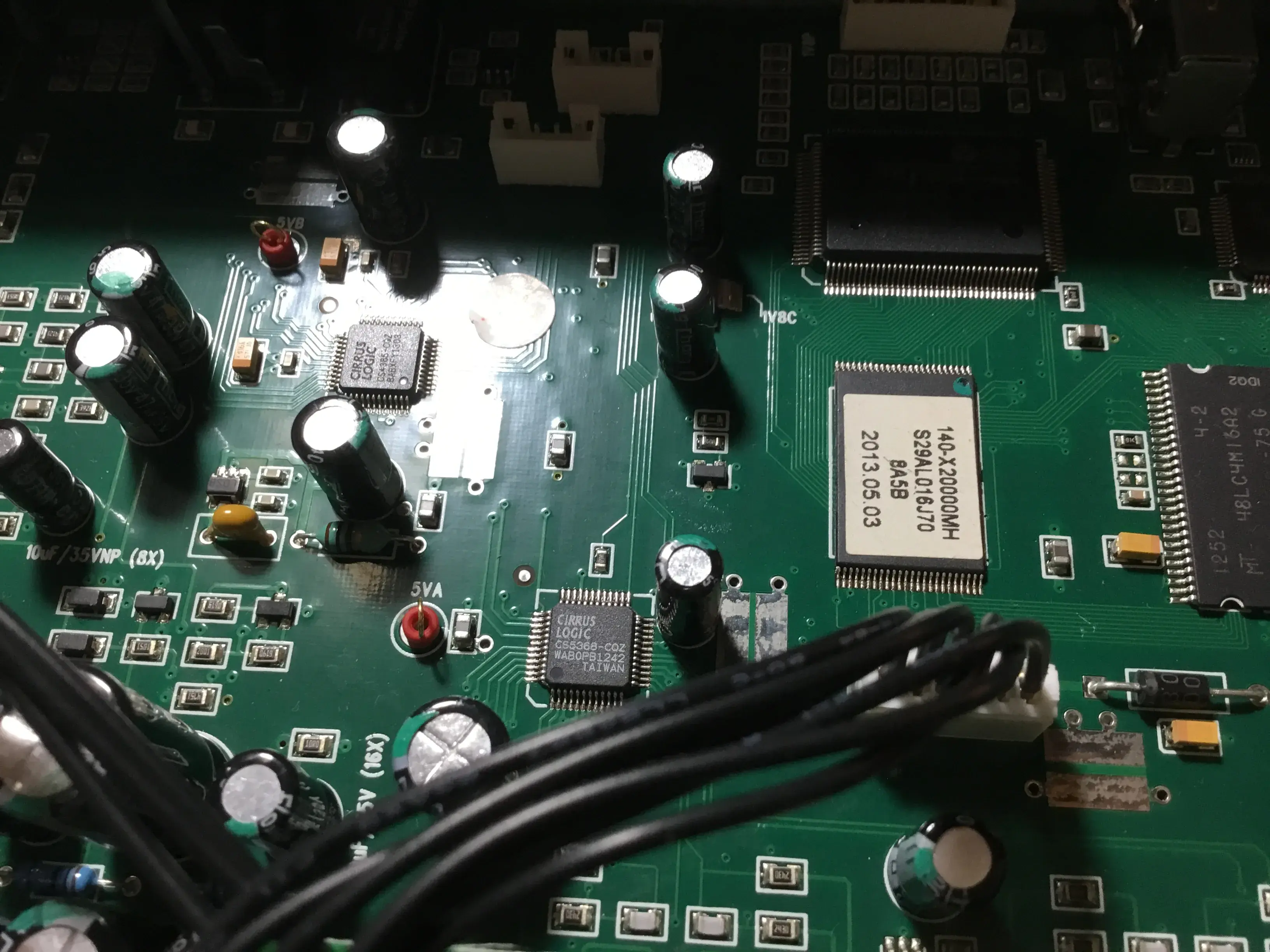
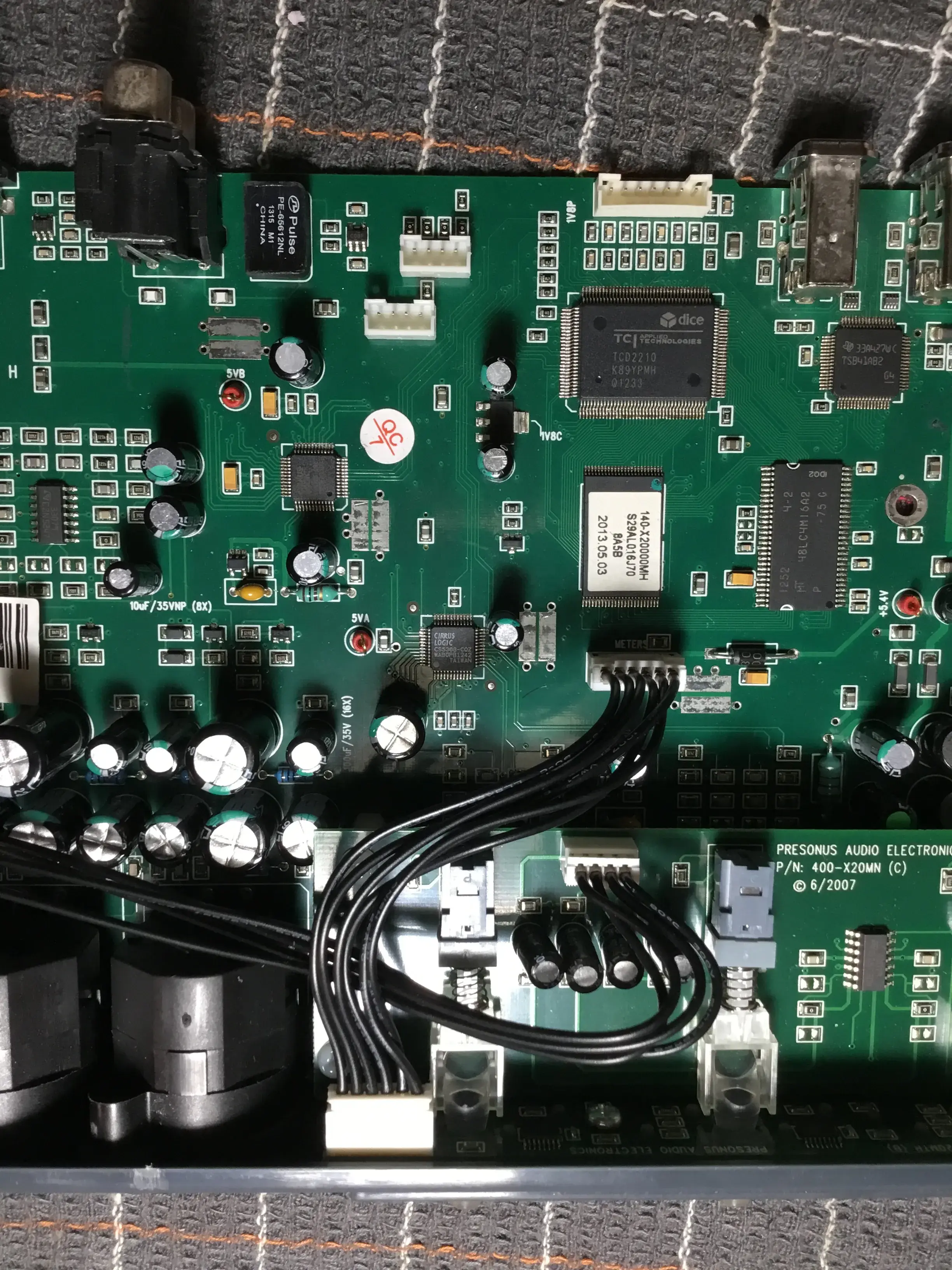
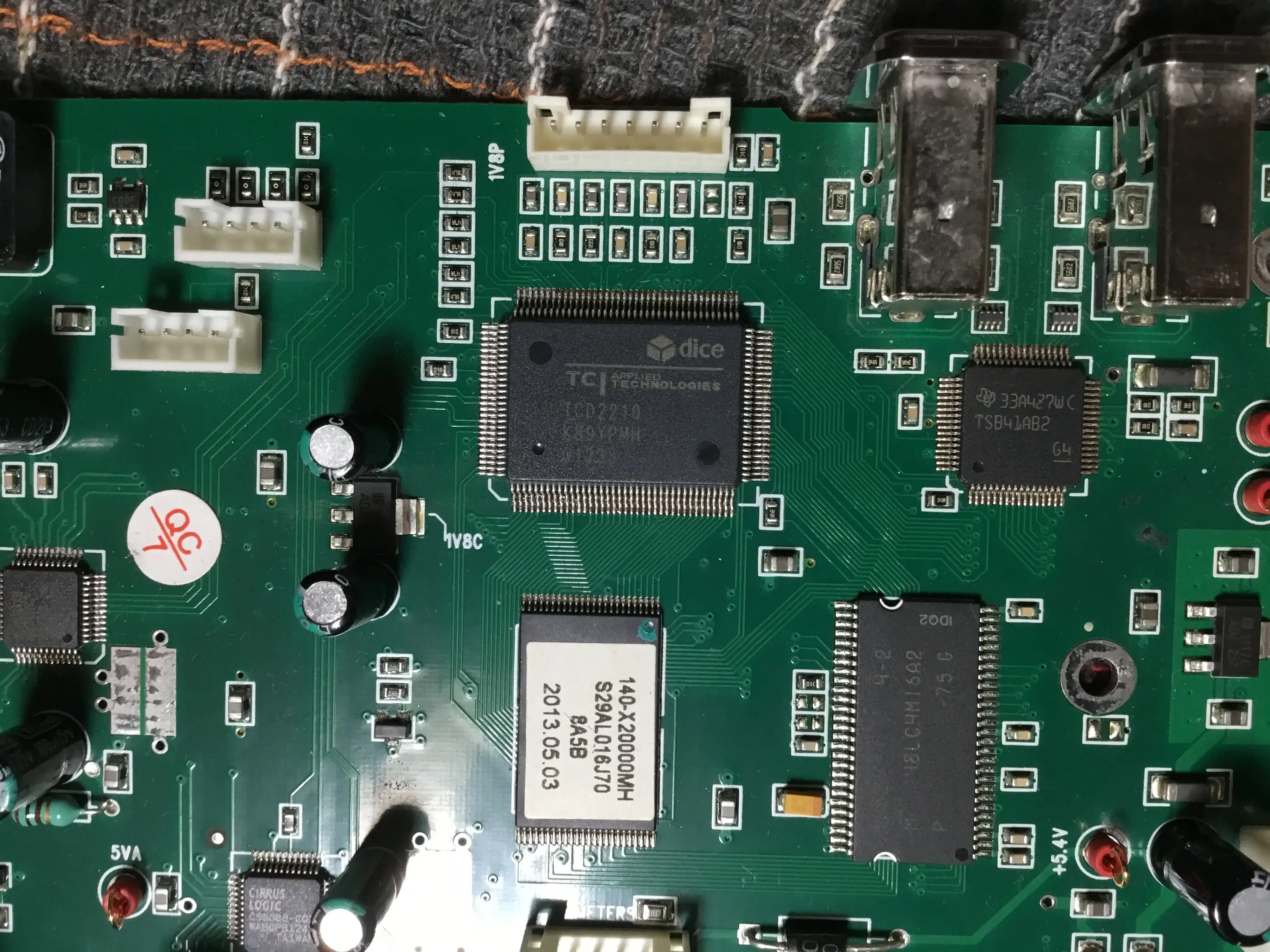
| Main MCU | TC Applied Technologies TCD2210 (Dice Mini) |
| RAM | Micron 48LC4M16A2 |
| Flash | Cypress S29AL016J70 |
| Firewire PHY | Texas Instruments TSB41AB2 |
| Audio ADC | (1 x 8 channels) Cirrus Logic CS5368 |
| Audio DAC | (1 x 8 channels) Cirrus Logic CS4385 |
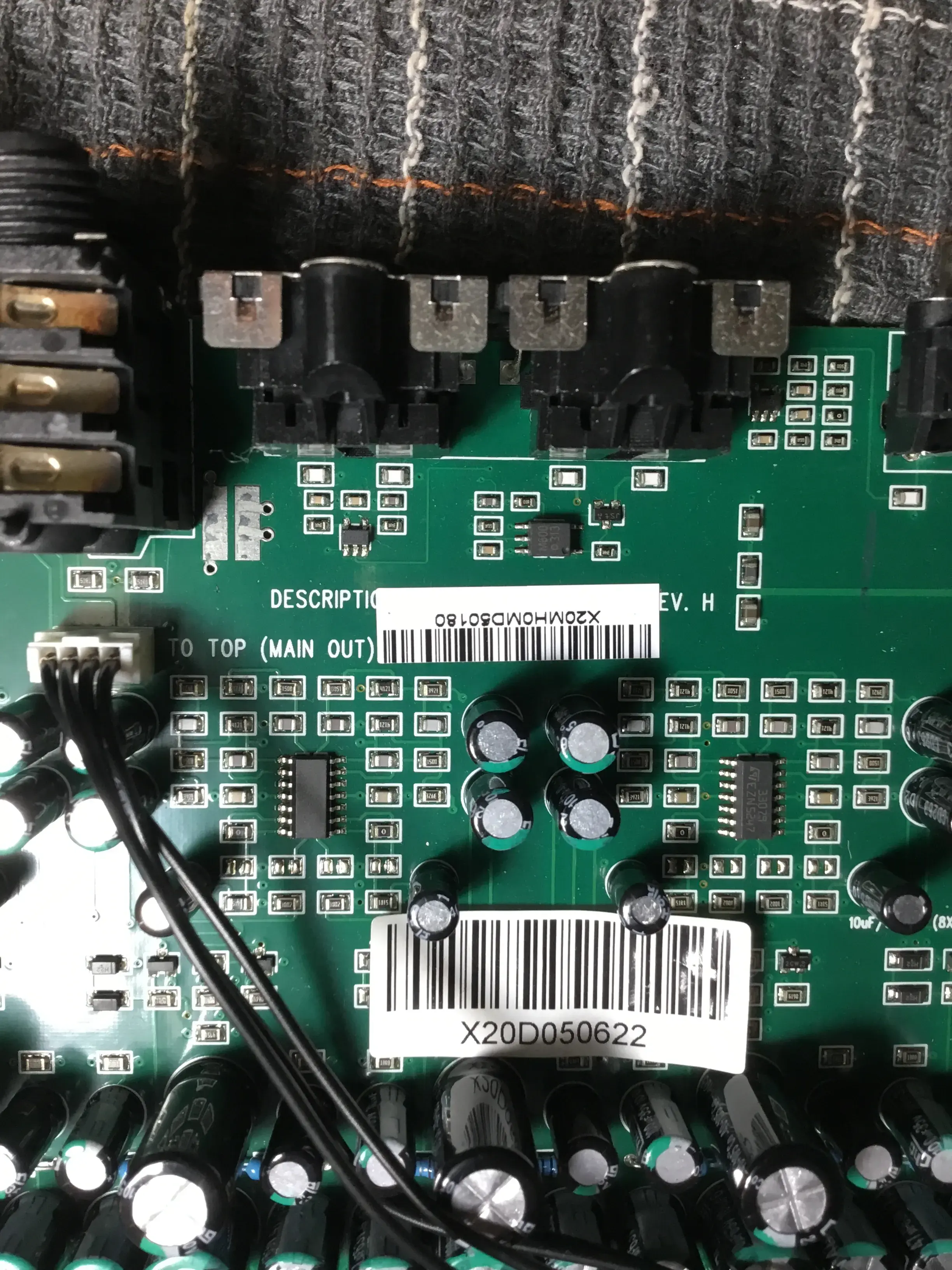
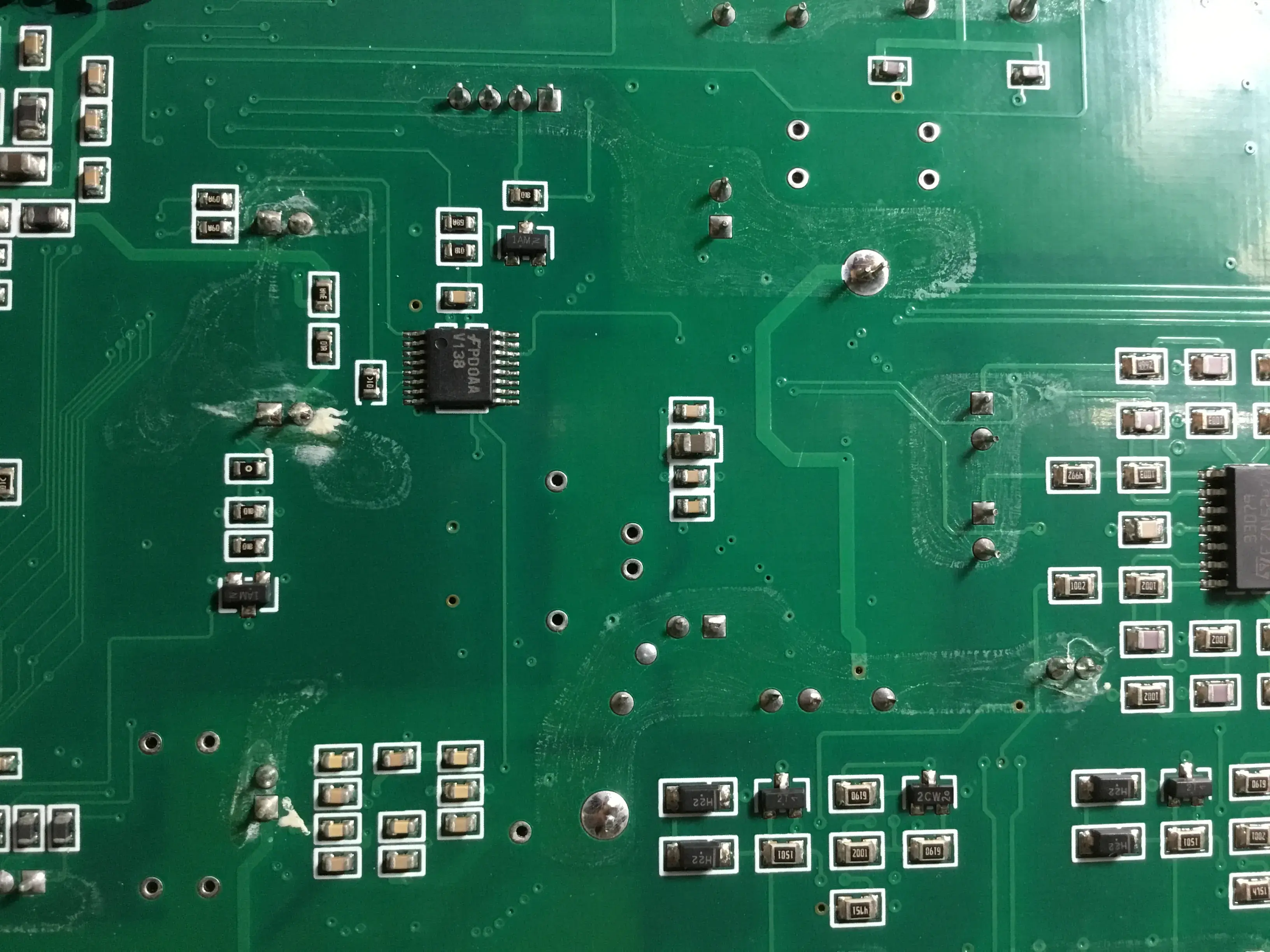
| SPI Multiplexer | Fairchild V138 74VHC138 |
| Vumeters Shift Register | Fairchild V595 74VHC595 |
Guide
Build firmware and flash it
Clone the fuegocable XMOS firmware repository and follow its README to build the firmware binary. From the repository root, configure and build the firmware for this board and interface:
cmake -B build
cmake --build build --target dxio_mc_3w_presonus_firestudio_project
Use an XTAG connected to the board's XSYS header to flash the firmware. USB DFU may also be an option, but it has not been tested.
Prepare xmos board
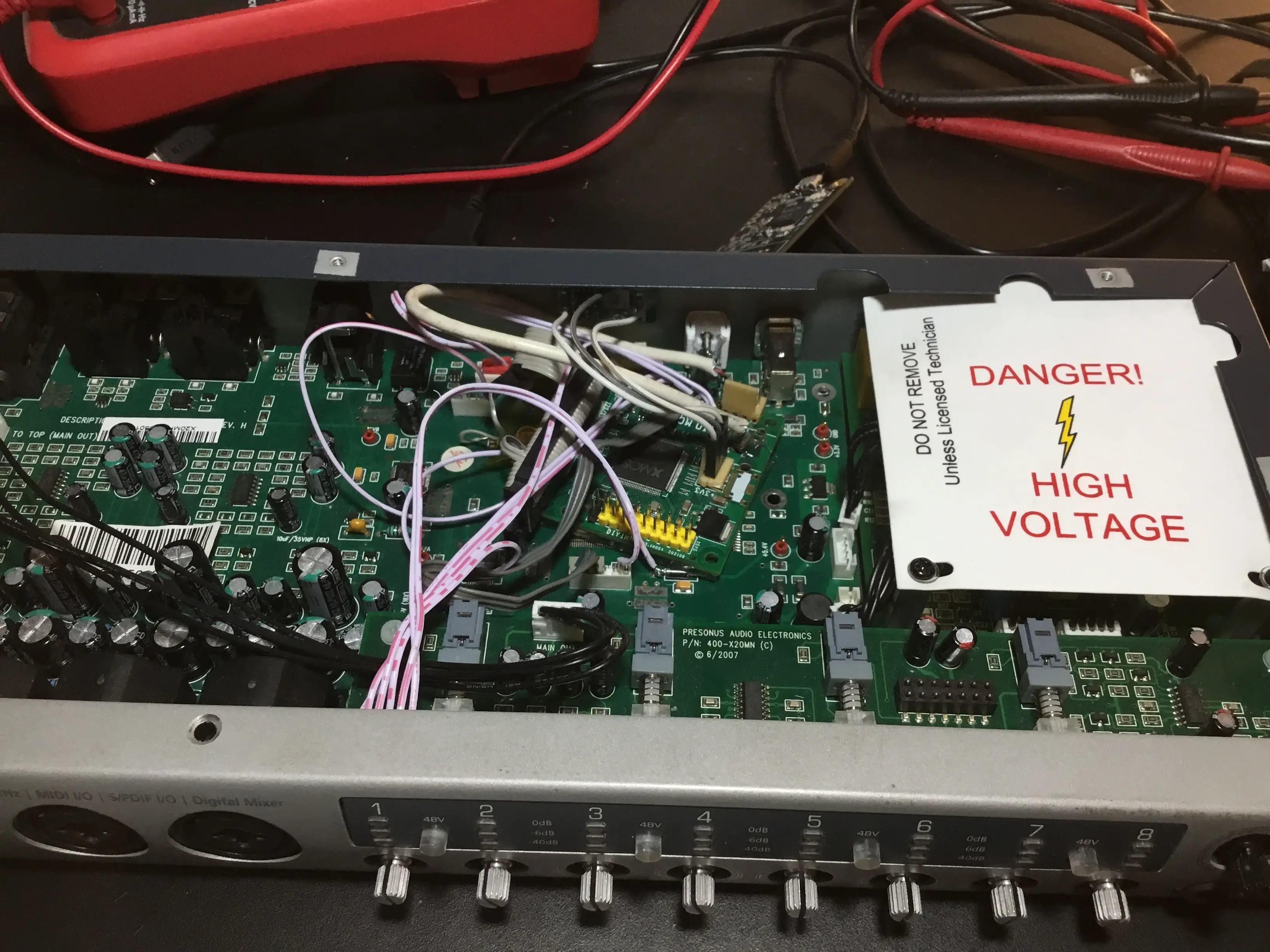
This guide uses the DIYINHK DXIO MC (3W), but other XMOS-based boards can also be used, as long as all the required Presonus Firestudio Project signals are connected to the appropriate XMOS chip ports. The board needs a 3.3V supply. In this build, an MP1584-based module was connected to the board's 3.3V/5V/GND header.
This board usually comes with a USB connector already installed. Remove it to free up the USB port traces, the USB-C connector will later be mounted on the audio interface chassis and wired to the board.
Remove components
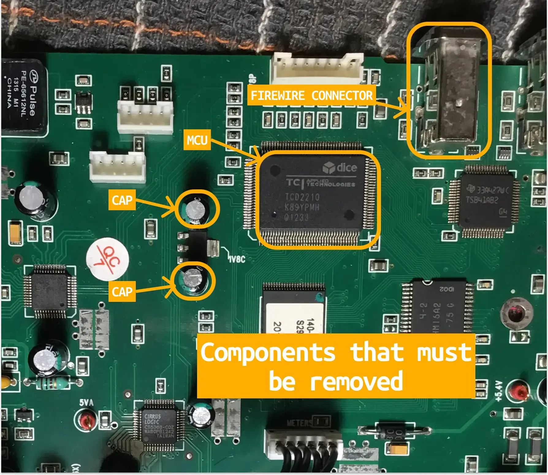
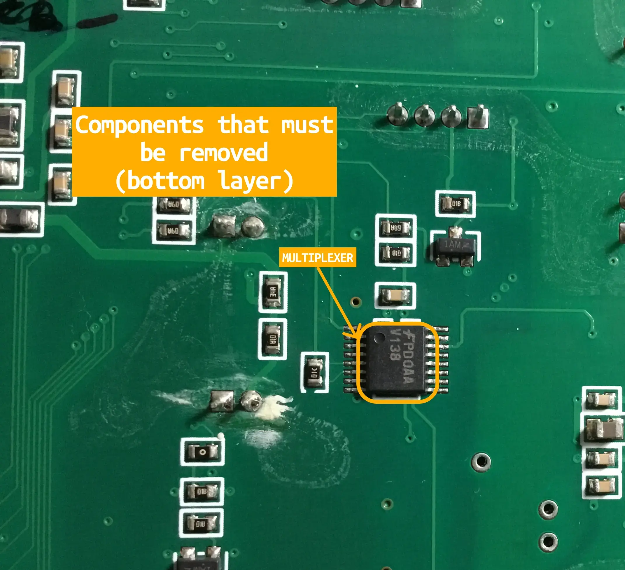
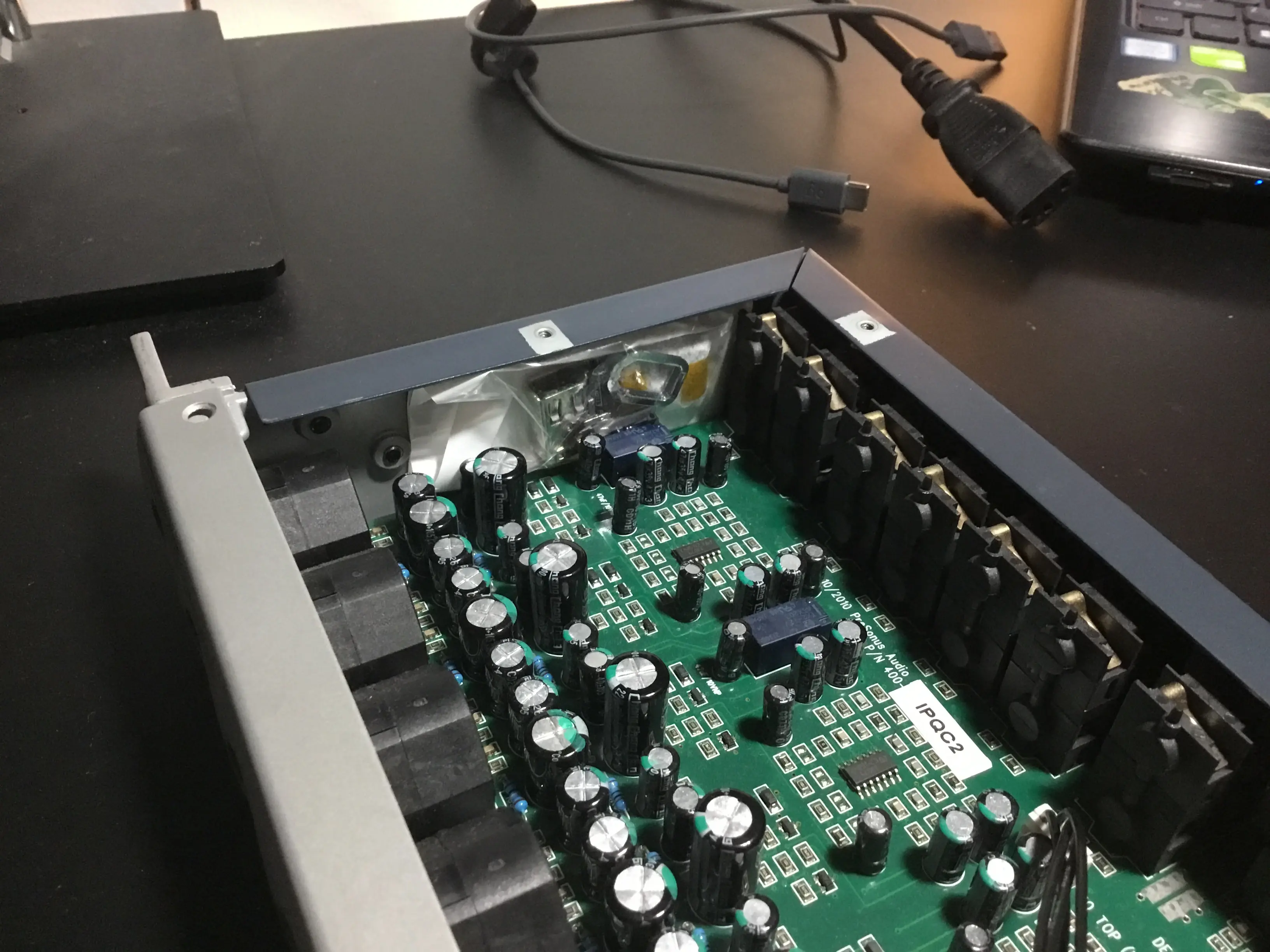
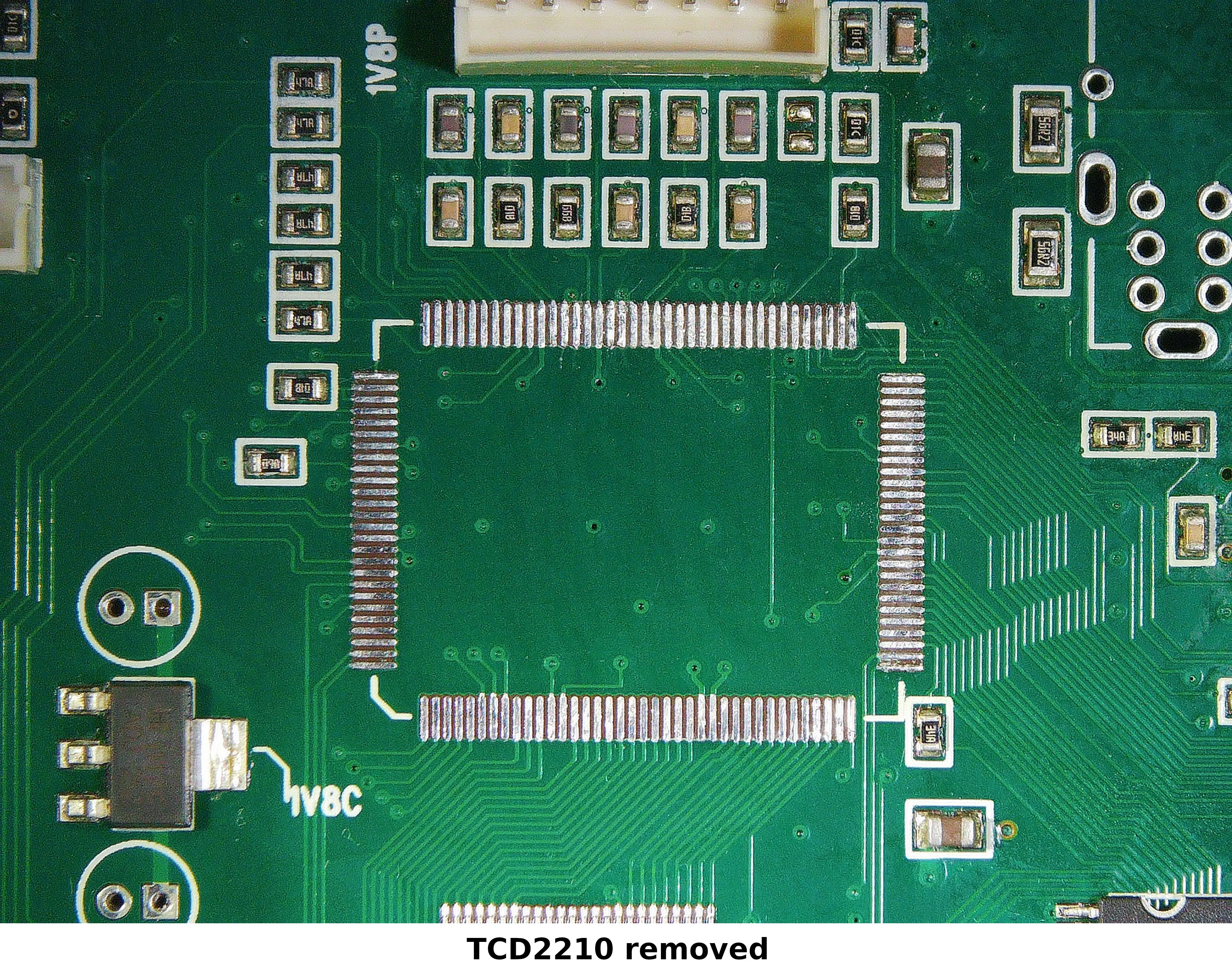
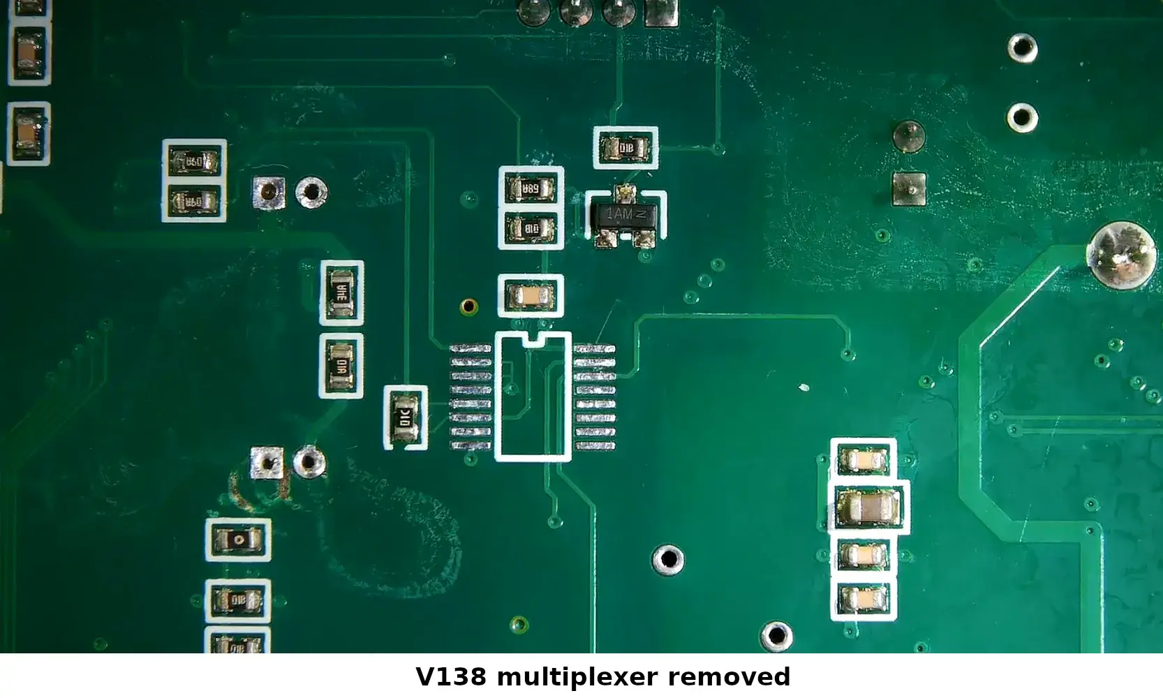
To perform the mod, you need to remove a few components. From the top side of the PCB, remove two capacitors, the TCD2210 MCU, and the FireWire connector that will be replaced by the USB-C port. Ideally, remove the connector farthest from the interface's power supply. From the bottom side of the PCB, remove the multiplexer IC.
Solder wire bridge
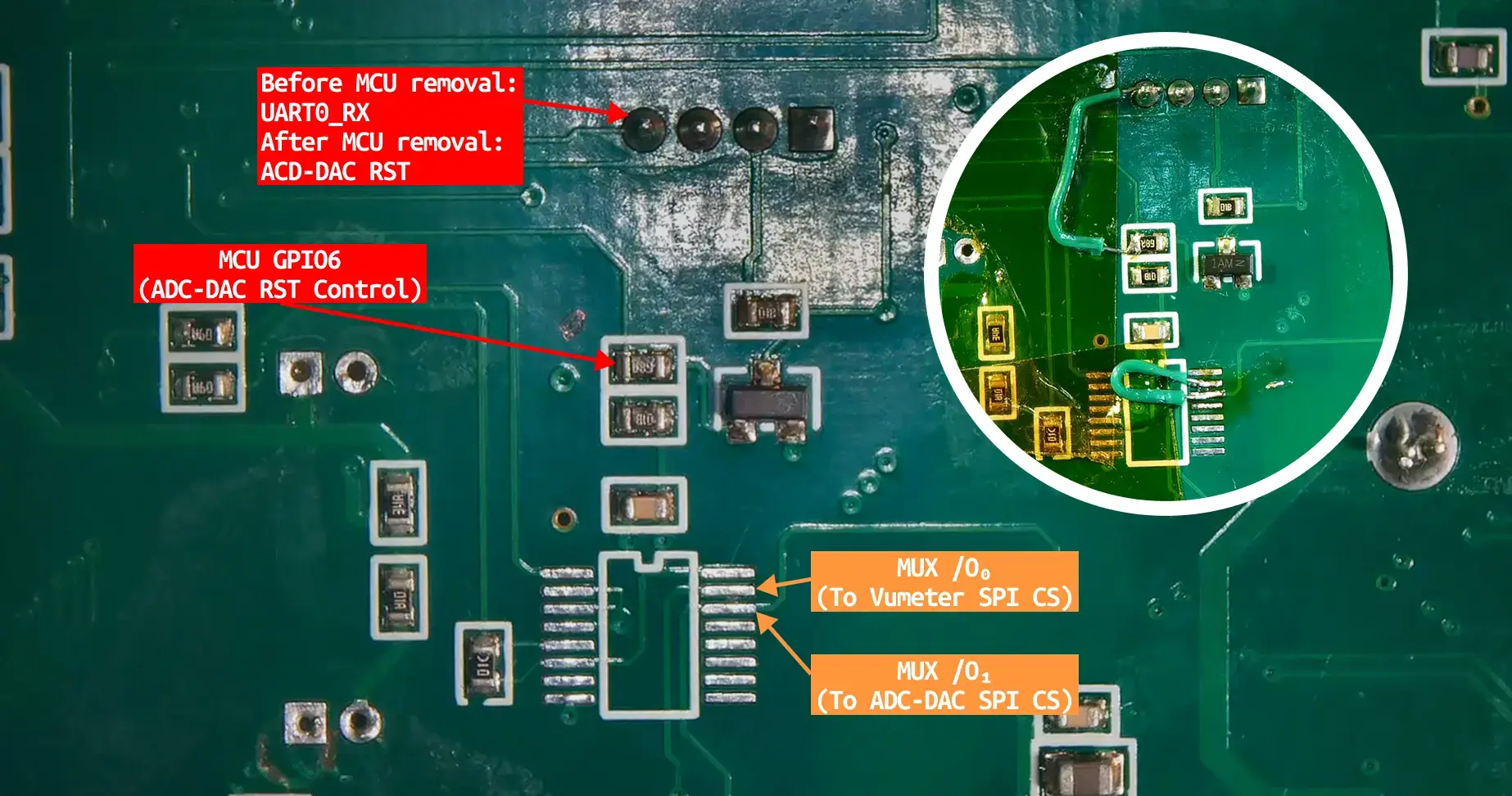
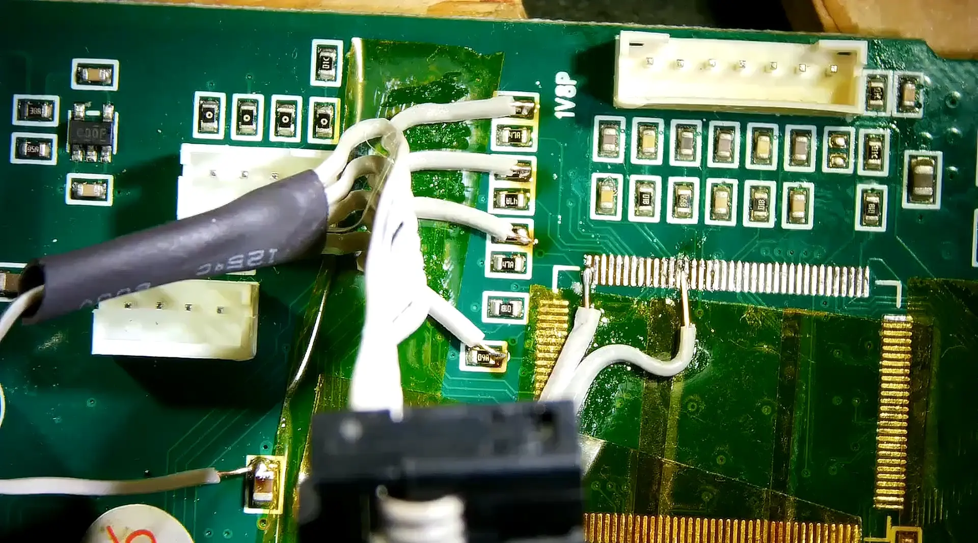
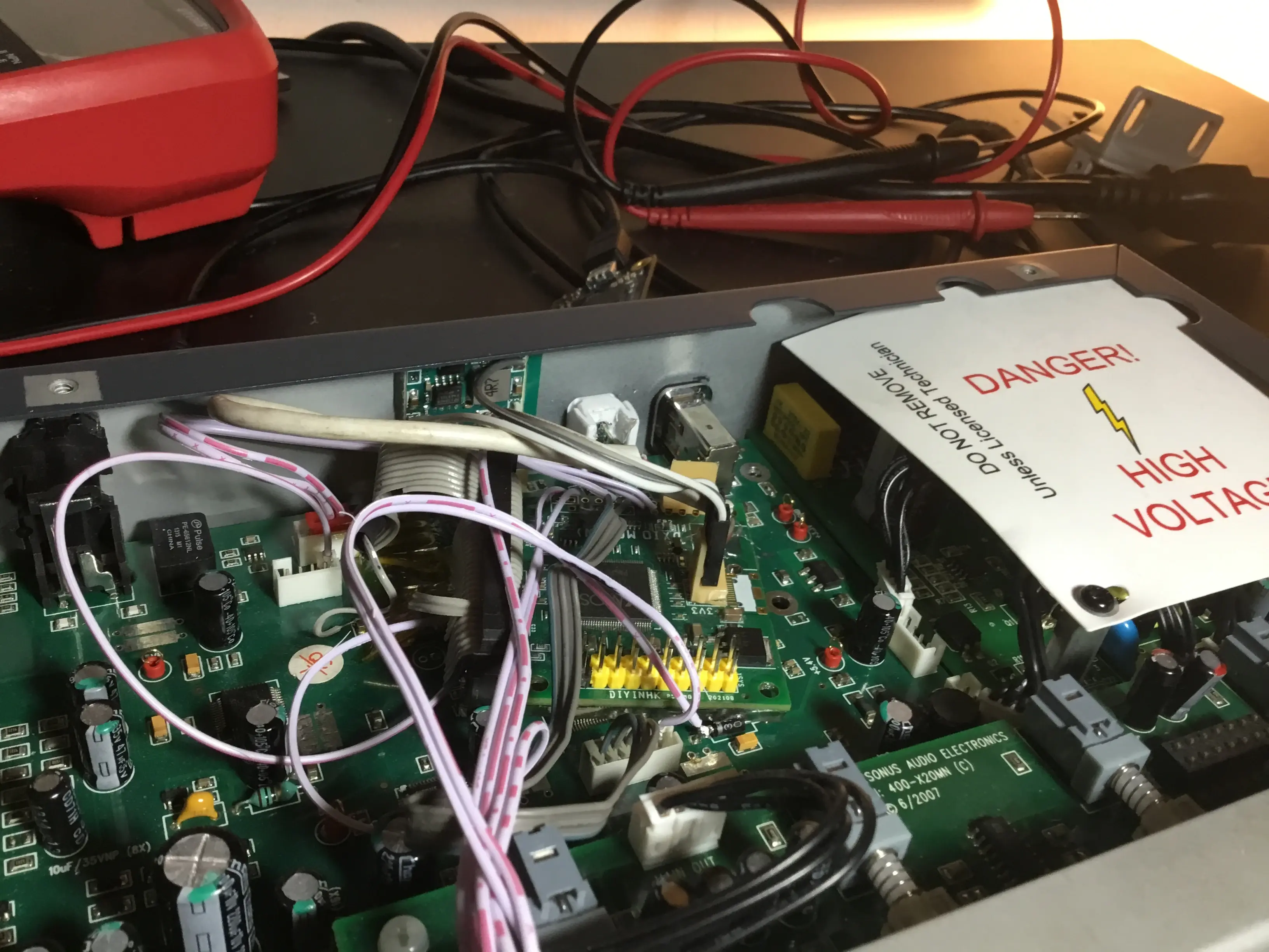
On the bottom side of the PCB, where the multiplexer was removed, make two wire bridges.
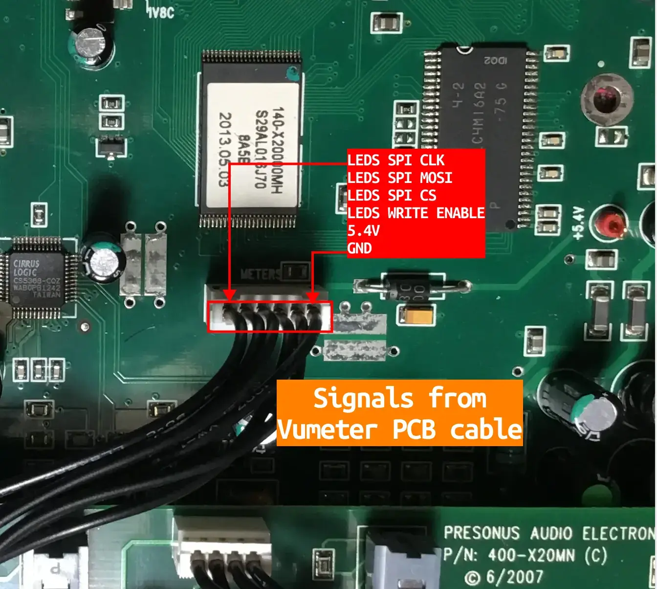
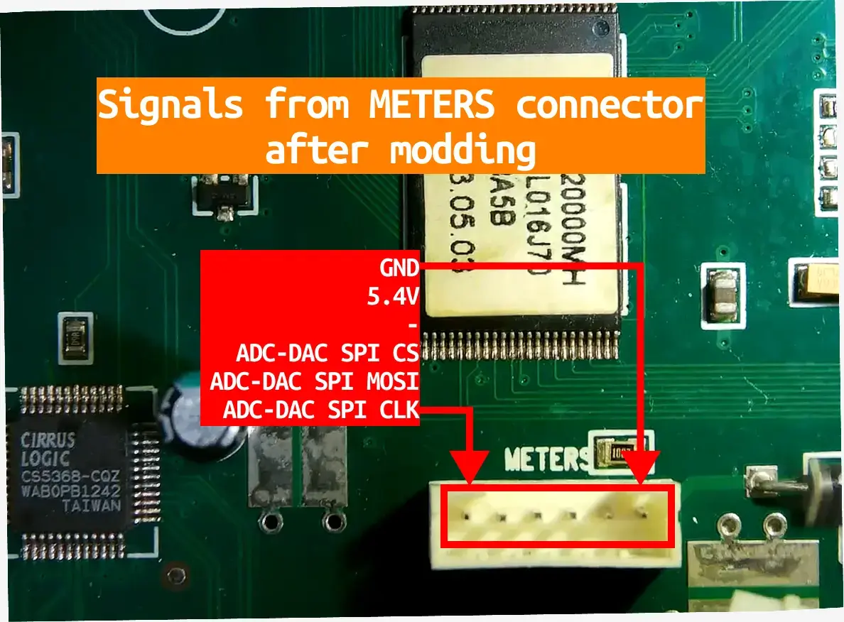
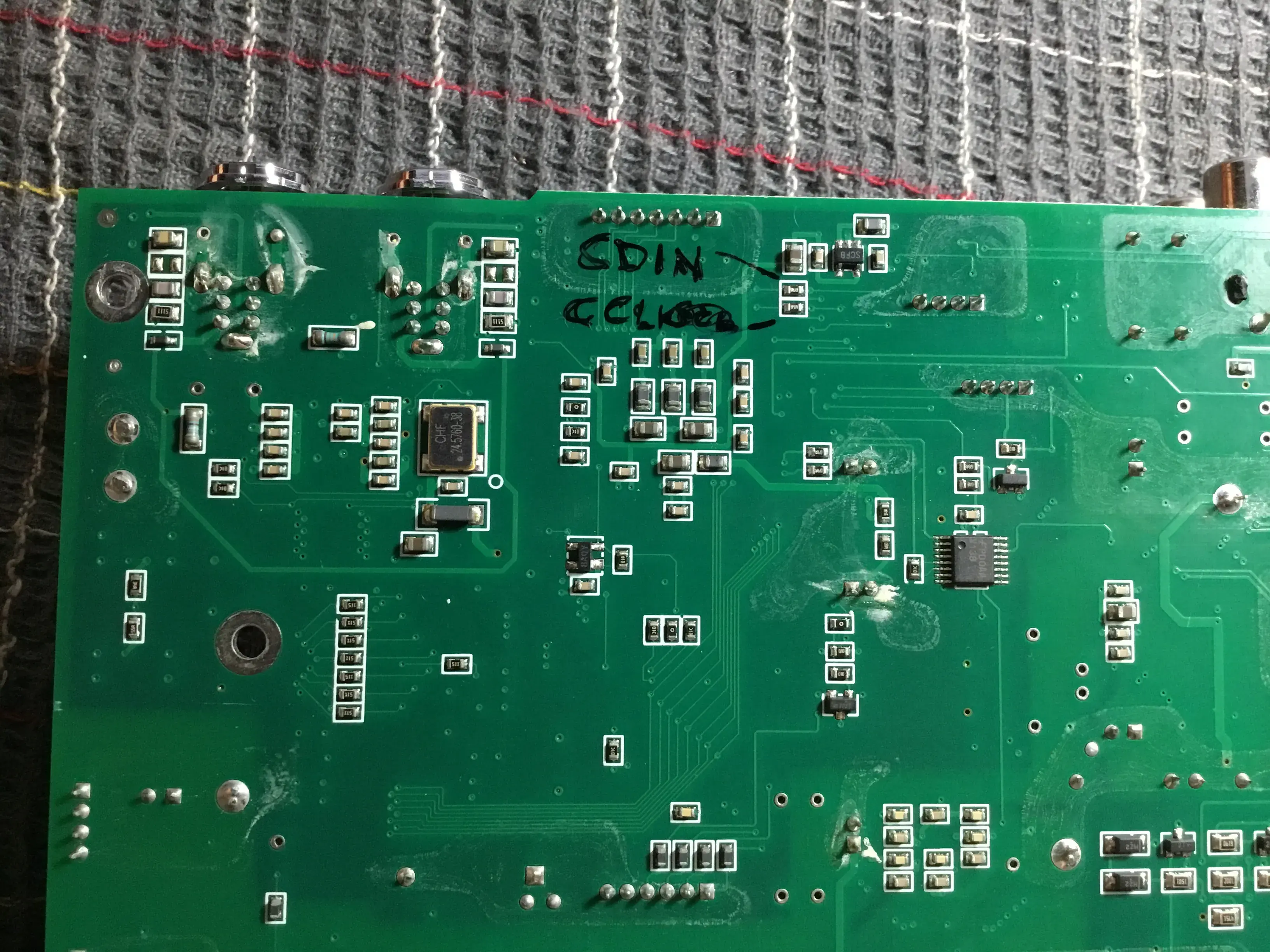
One of them bridges the multiplexer outputs /O0 and /O1. These carry the shared SPI chip-select signal for the ADC and DAC, and the SPI chip-select signal for the LED meters, respectively. This makes the converters' SPI chip-select signal available at the connector on the top side of the main PCB that connects to the meter PCB.
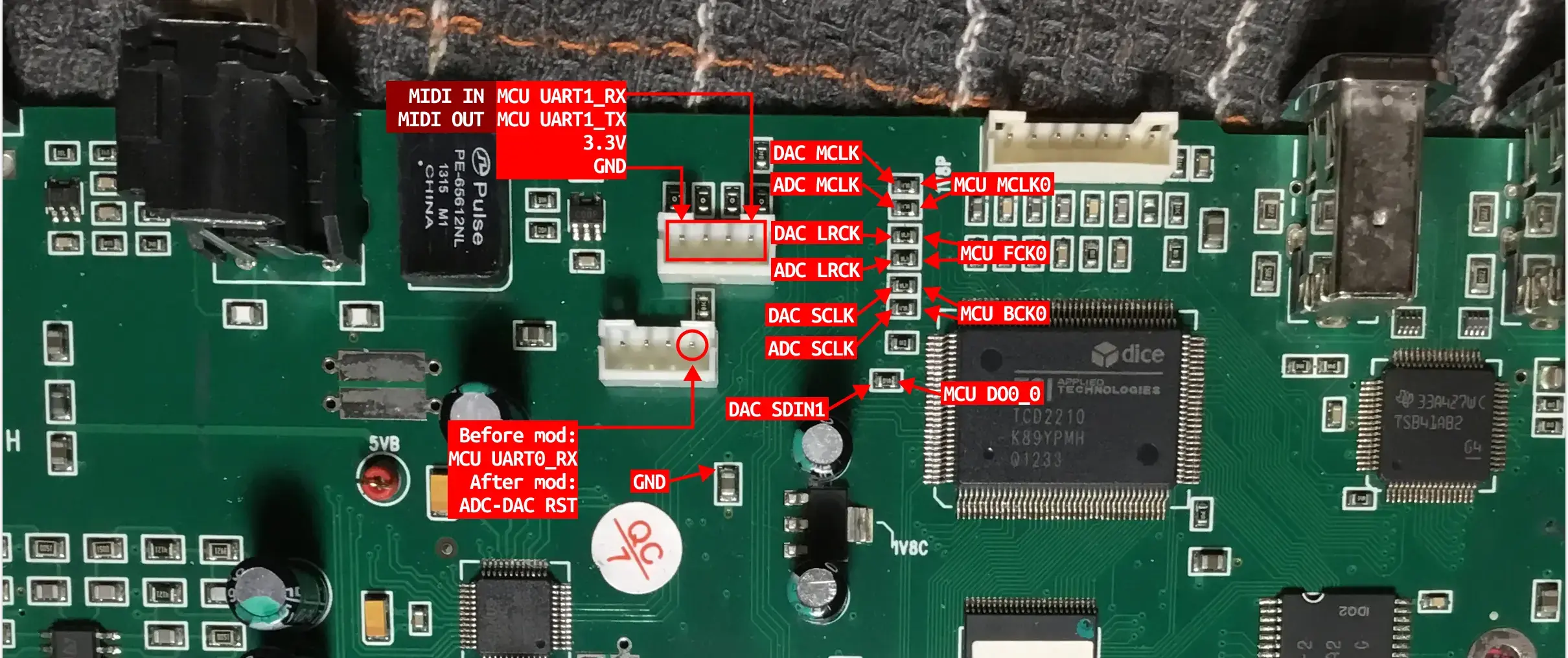
The other bridges the converters RST signal (which originally is a GPIO from the original MCU) to a connector on the top side of the main PCB (the one with the original MCU's UART 0).
Before soldering, apply Kapton tape to the PCB. Once the wires are soldered, secure them to the tape with cyanoacrylate. The tape keeps the glue off the PCB, so the mod can be reversed cleanly by removing the tape.
Solder wires
Connect all required signals between the audio interface's main PCB and the XMOS board running the fuegocable firmware. The following tables have the signals to connect to the XMOS board, grouped by connector on the DXIO MC (3W). See the DXIO MC (3W) pinout for the board header pin assignments.
| Original PCB Ref | fuegocable function | Presonus FSP Signal | Pin N° | Pin N° | Presonus FSP Signal | fuegocable function | Original PCB Ref |
|---|---|---|---|---|---|---|---|
| RST_ADC | - | - | 1 | 2 | - | - | GND |
| DIO1 | PORT_I2S_ADC0 | MCU DI0_0 | 3 | 4 | GND | - | GND |
| DIO2 | - | - | 5 | 6 | - | - | GND |
| DIO3 | - | - | 7 | 8 | - | - | GND |
| DIO4 | - | - | 9 | 10 | - | - | GND |
| SDA | - | - | 11 | 12 | - | - | GND |
| SCL | - | - | 13 | 14 | - | - | GND |
| 48K=1 | - | - | 15 | 16 | ADC-DAC RST | P_ADC_DAC_RESET_GPIO | RSTDAC |
| DSP | - | - | 17 | 18 | MCU GPIO8 | P_METERS_OUTPUT_ENABLE_N_GPIO | DSDON |
| ADCRST | - | - | 19 | 20 | - | - | NC (3.3V) |
| DIN | - | - | 21 | 22 | - | - | GND |
| DATA | PORT_I2S_DAC0 | MCU DO0_0 | 23 | 24 | GND | - | GND |
| BCK | PORT_I2S_BCLK | MCU BCK0 | 25 | 26 | GND | - | GND |
| LRCK | PORT_I2S_LRCLK | MCU FCK0 | 27 | 28 | GND | - | GND |
| MCK | PORT_MCLK_IN | MCU MCLK0 | 29 | 30 | GND | - | GND |
| DO2 | - | - | 31 | 32 | - | - | GND |
| DO3 | - | - | 33 | 34 | - | - | GND |
| DO4 | - | - | 35 | 36 | - | - | GND |
| X01D | - | - | 37 | 38 | - | - | GND |
| X01A | - | - | 39 | 40 | - | - | GND |
| Original PCB Ref | fuegocable function | Presonus FSP Signal | Pin N° | Pin N° | Presonus FSP Signal | fuegocable function | Original PCB Ref |
|---|---|---|---|---|---|---|---|
| GND | - | - | 1 | 2 | - | - | GND |
| 3.3V | - | - | 3 | 4 | - | - | 3.3V |
| - | - | - | 5 | 6 | - | - | - |
| - | - | - | 7 | 8 | - | - | - |
| - | PORT_MIDI_IN | UART1_RX | 9 | 10 | - | - | - |
| - | PORT_MIDI_OUT | UART1_TX | 11 | 12 | - | - | - |
| - | - | - | 13 | 14 | ADC-DAC SPI CS | ADC_DAC_SPI_SS_BIT | - |
| - | PORT_SPI_SCLK | MCU SPIA_CK | 15 | 16 | METERS SPI CS | METERS_SPI_SS_BIT | - |
| - | - | - | 17 | 18 | - | - | - |
| - | PORT_SPI_MOSI | MCU SPIA_MOSI | 19 | 20 | - | - | - |
| GND | - | - | 21 | 22 | - | - | GND |
| EXTOSCFWR | - | - | 23 | 24 | - | - | SPDIFOUT |
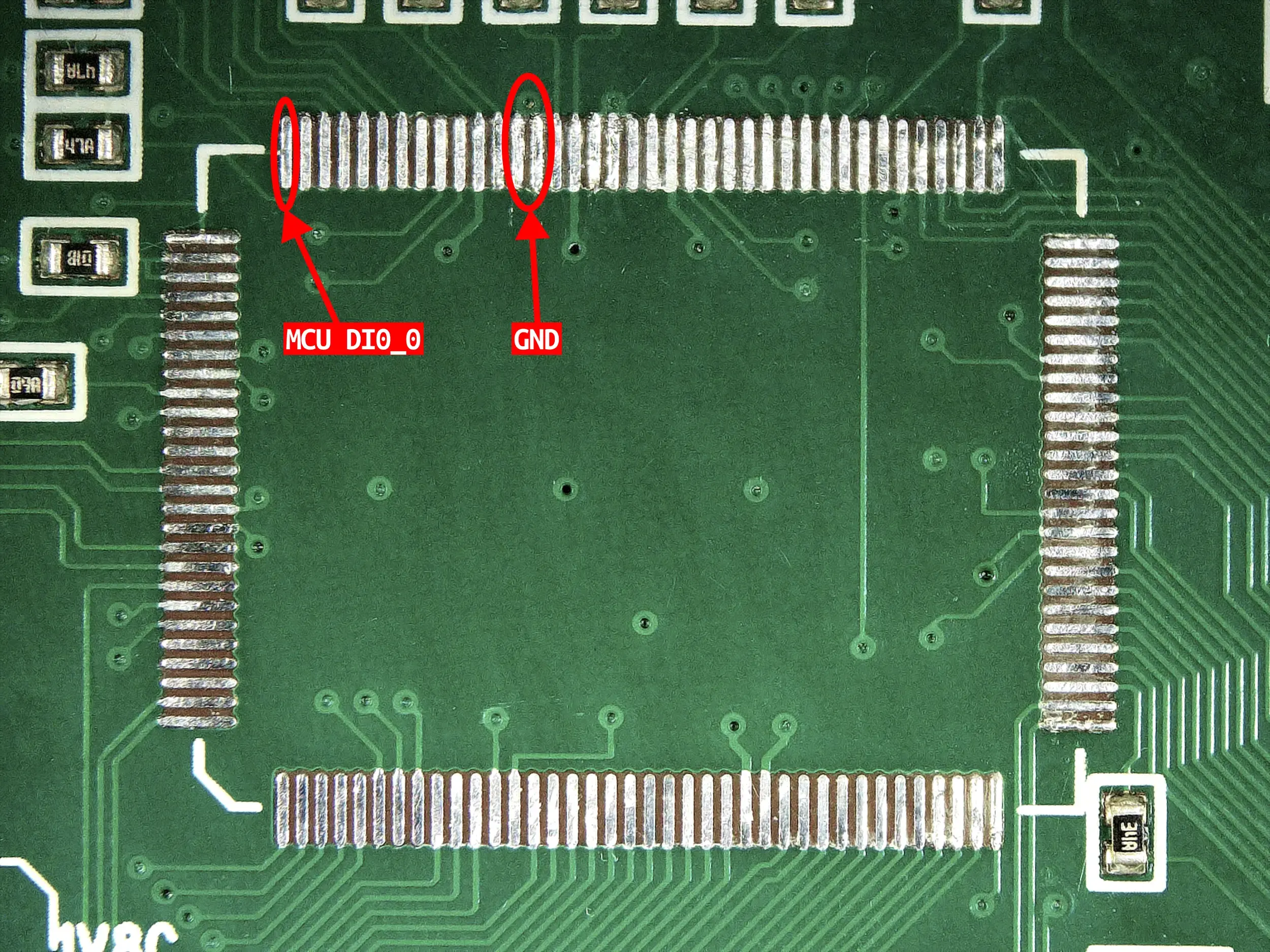
Take particular care with the digital audio signals (MCU MCLK0, MCU FCK0, MCU DO0_0, and MCU DI0_0). They form a TDM bus with clock lines, so all bus signals must arrive in sync, with as little interference as possible to minimize jitter. A ribbon cable with an IDC connector is recommended, with ground conductors interleaved between signal conductors in a G-S-G-S-G pattern so each signal has its own ground, and all wires should be the same length.
All but one of the audio bus signals can be tapped from one edge of some specific resistors, which makes soldering easier. MCU DI0_0 must be soldered directly to a trace on the original MCU footprint. This takes a little more care and experience, but is manageable.
USB C connector and mount
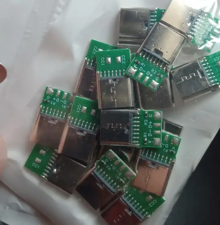
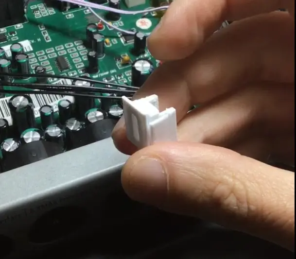
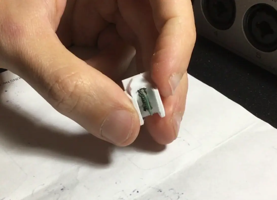
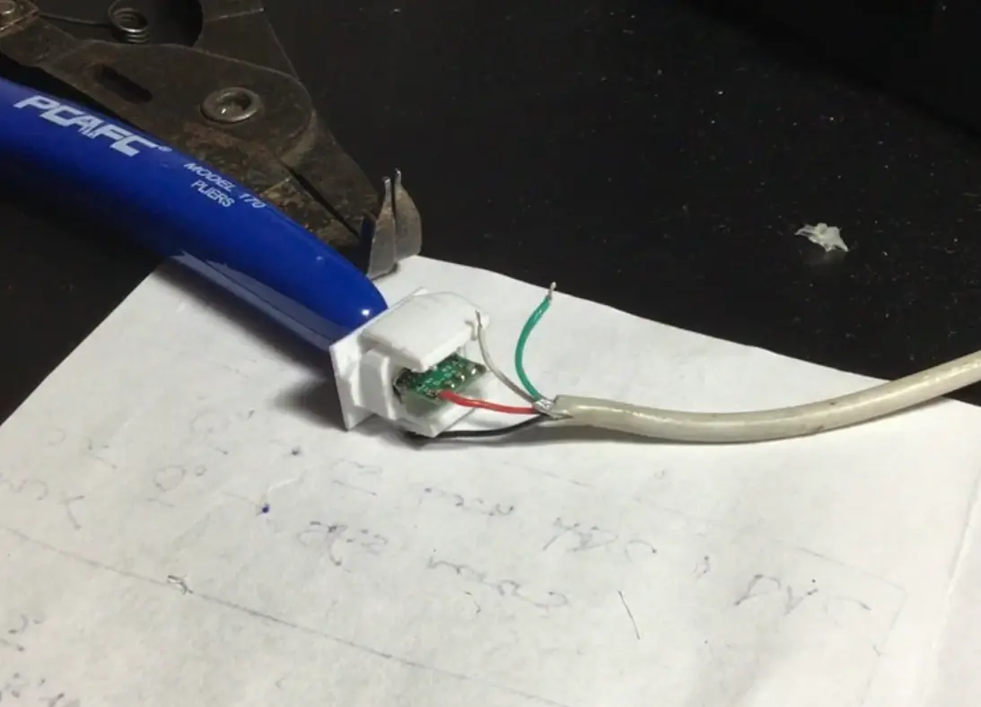
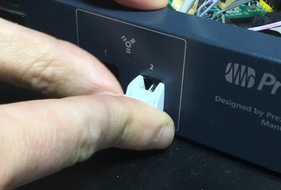
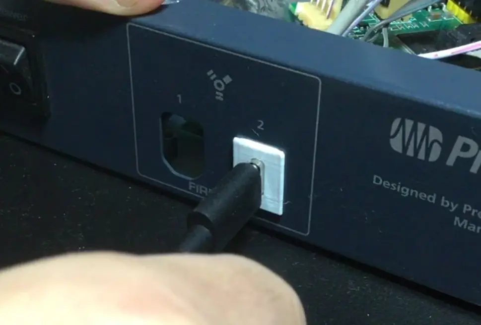
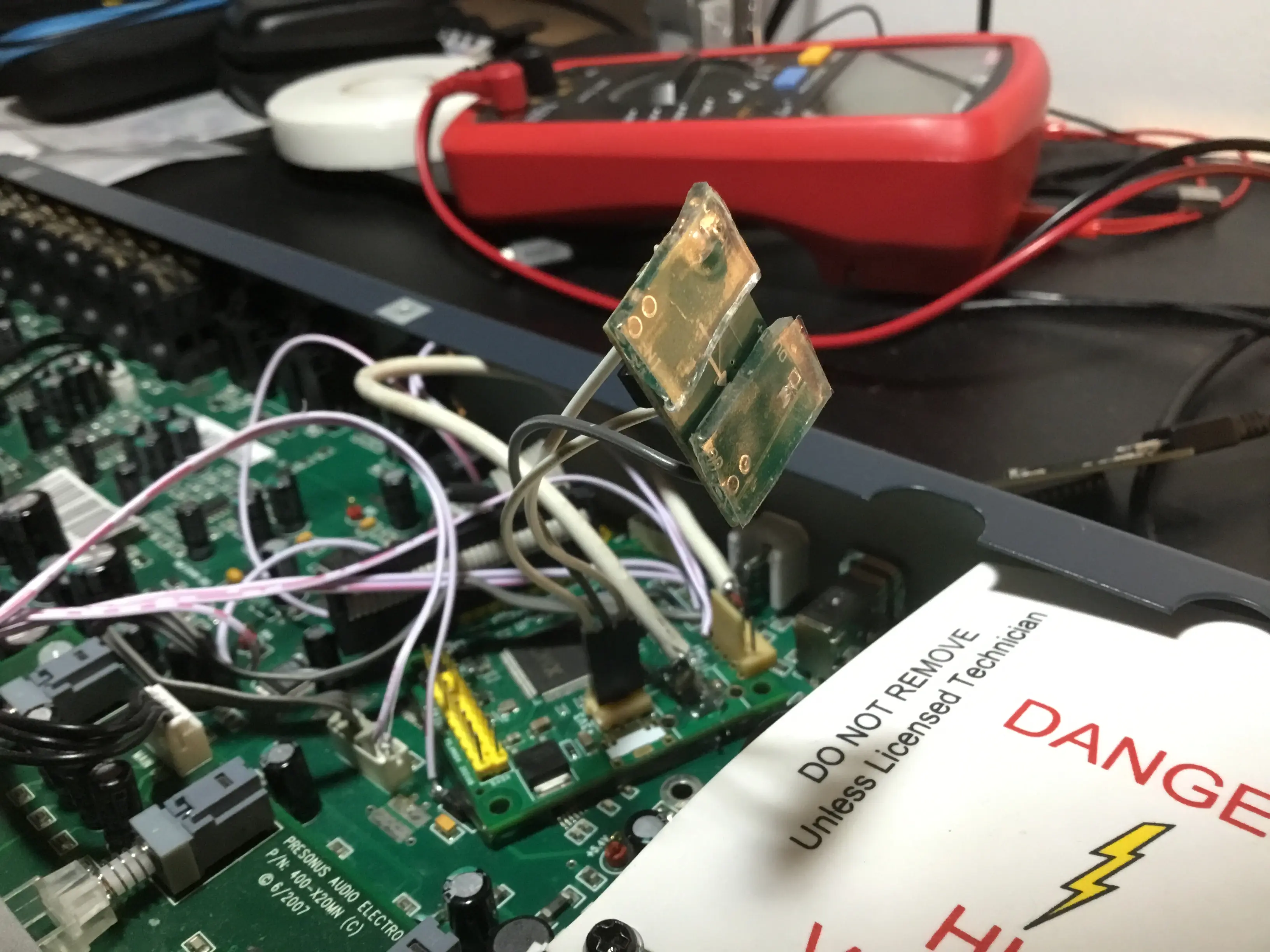
This interface uses one of the FireWire port openings in the chassis to mount the female USB-C port that connects to the host. A 3D-printed mount designed for that opening and a specific female USB-C module is available to download and print . The module fits the chassis opening and the mount, and includes D+ and D- connections as well as resistors between certain USB-C pins to ensure a 5V supply when using USB-C power sources. Additionally, this USB-C module features a connector with four small metal tabs prefect to be bent, securing the module inside the 3D-printed mount.
3D model of USB C mount to print (3MF): presonus-fsp-usb-c-firewire-mount-v7.3mf
Final assembling
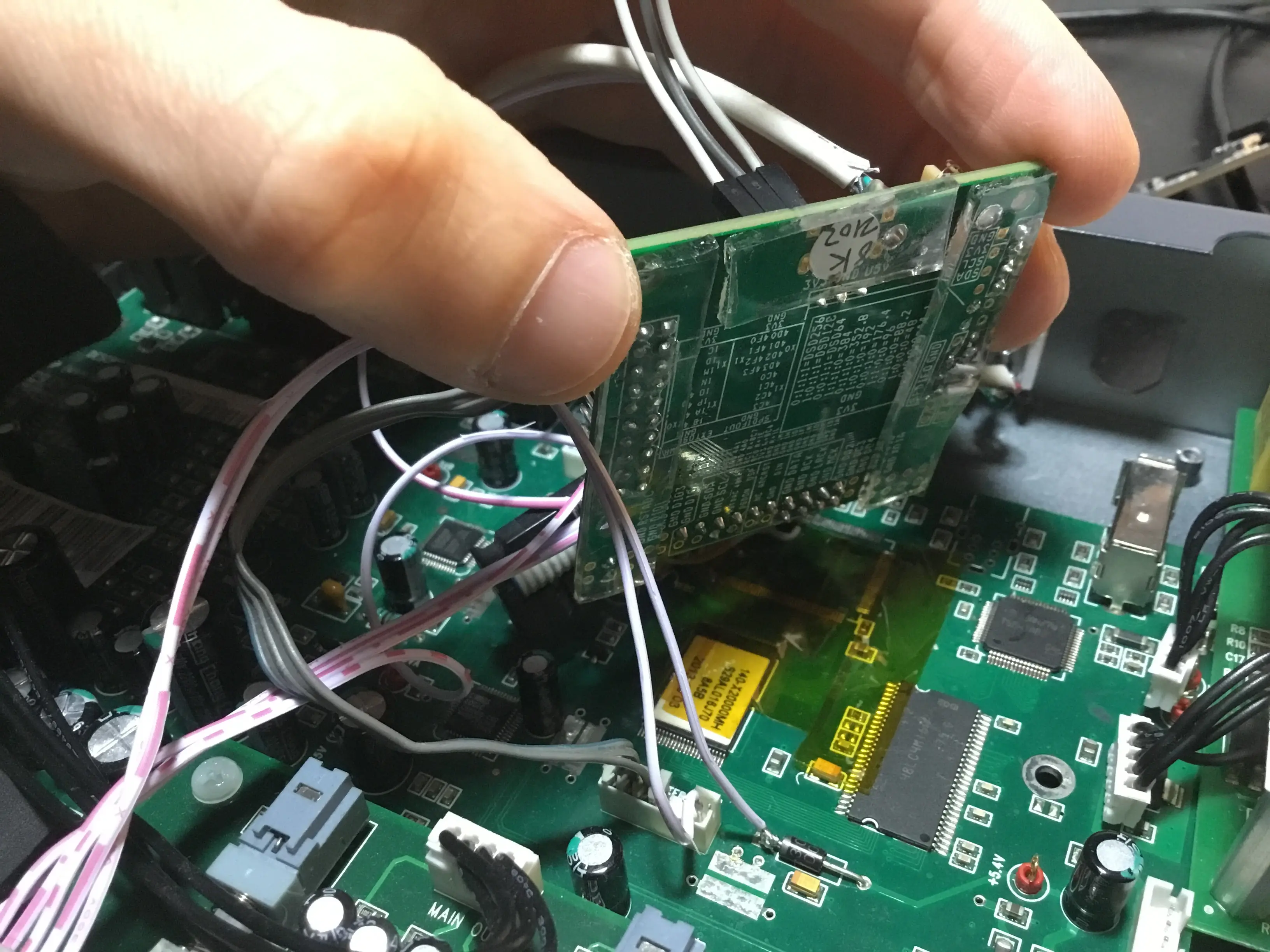
To finish the assembly, attach the XMOS board to the original PCB with durable double-sided tape. The 3.3V power module can be attached to an inside wall of the chassis.
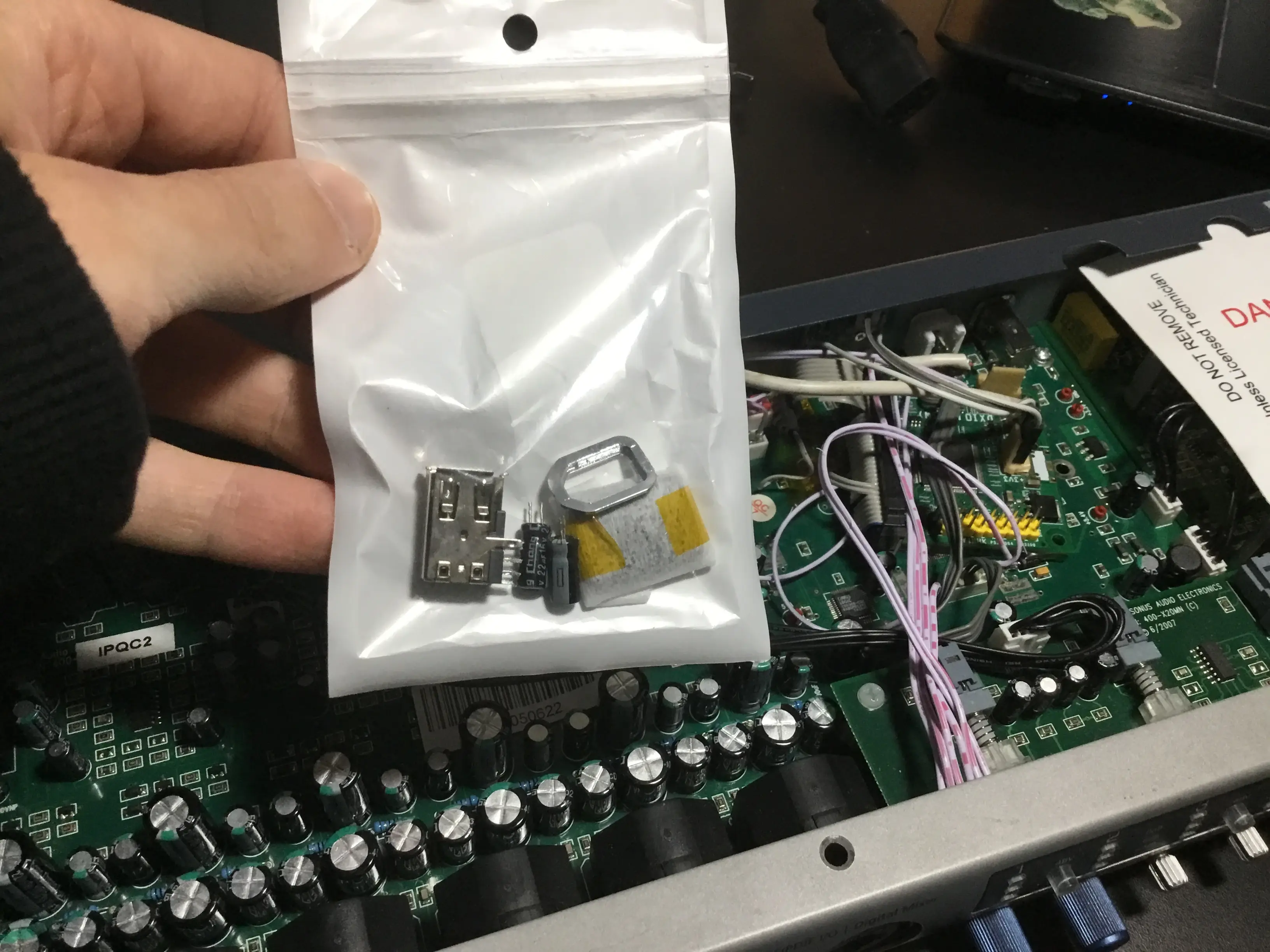
Keep all the removed original components together in a small bag and store it inside the interface, so they stay with the device. If you ever decide to reverse the mod, all the parts will be there.
Using it with a computer
The fuegocable XMOS firmware uses XMOS's lib_xua library, which provides a comprehensive implementation of USB Audio Class (UAC). Thats because on Linux and OS X, as well as iOS, iPadOS, Android, and any other UAC-compliant host, no additional drivers are required to use the interface.
On Windows, additional drivers are only required to access all 8 input and 8 output channels through ASIO. To achieve this, the firmware "emulates" a PreSonus AudioBox 1818 VSL interface. This is why, when you connect a modified interface to a computer, it is recognized as an AudioBox. So, simply install PreSonus's Universal Control driver, and you should be able to use all analog channels and MIDI ports normally with any application.
If you encounter any undocumented issues with your modified interfaces, please report them by opening an issue in the fuegocable XMOS firmware GitHub repository: https://github.com/fuegocable/xmos-firmware/issues

Additional data
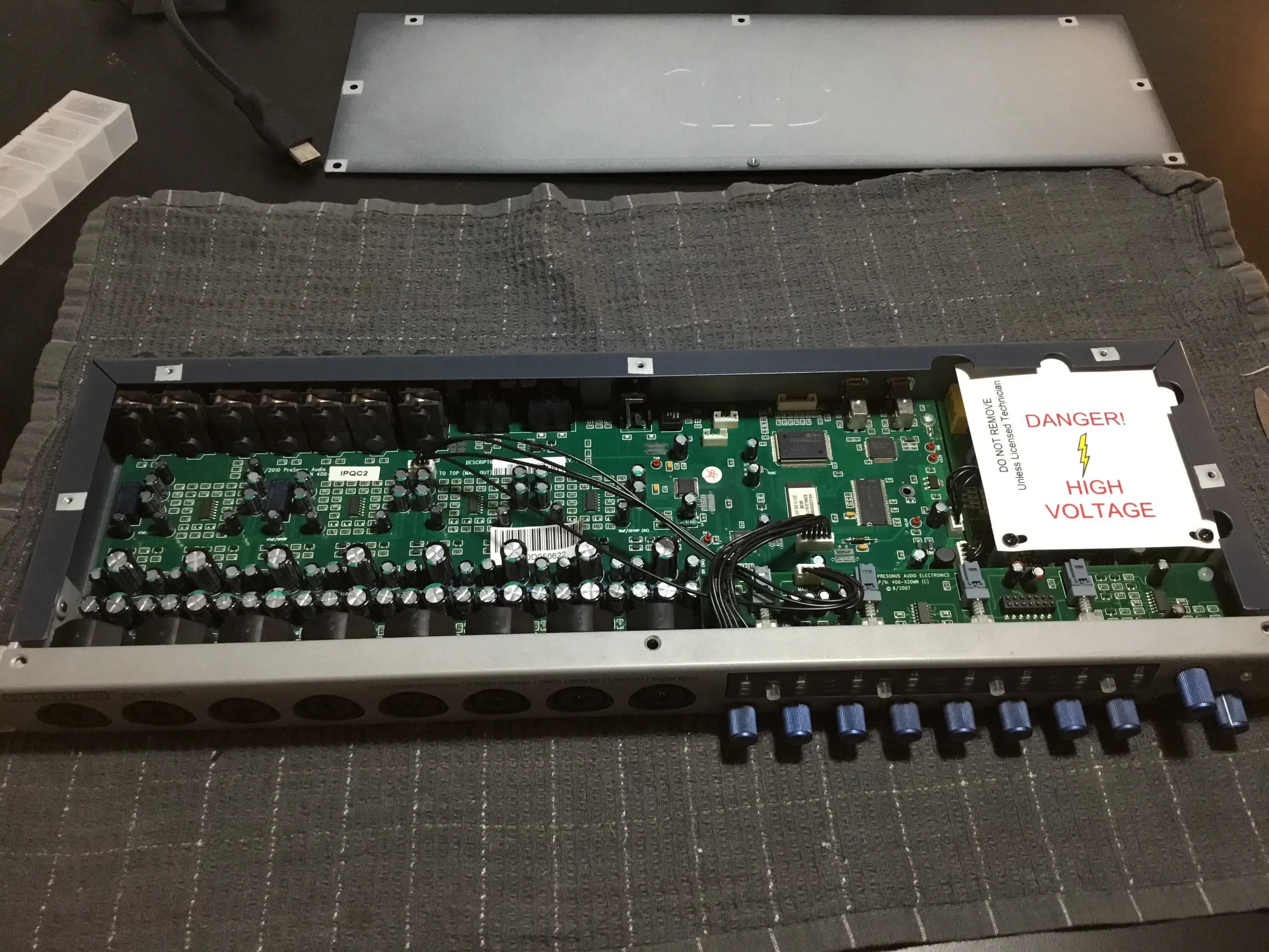
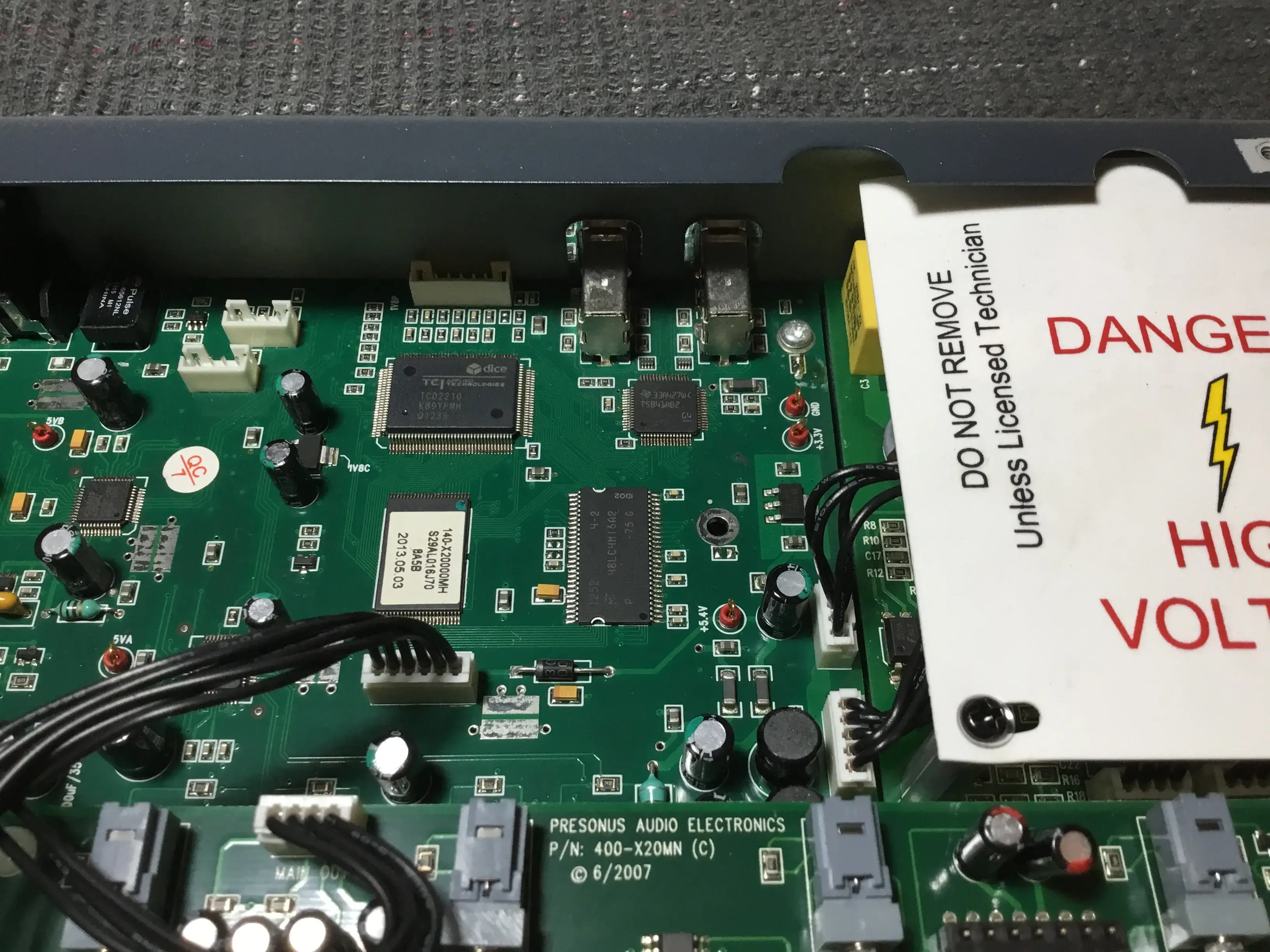
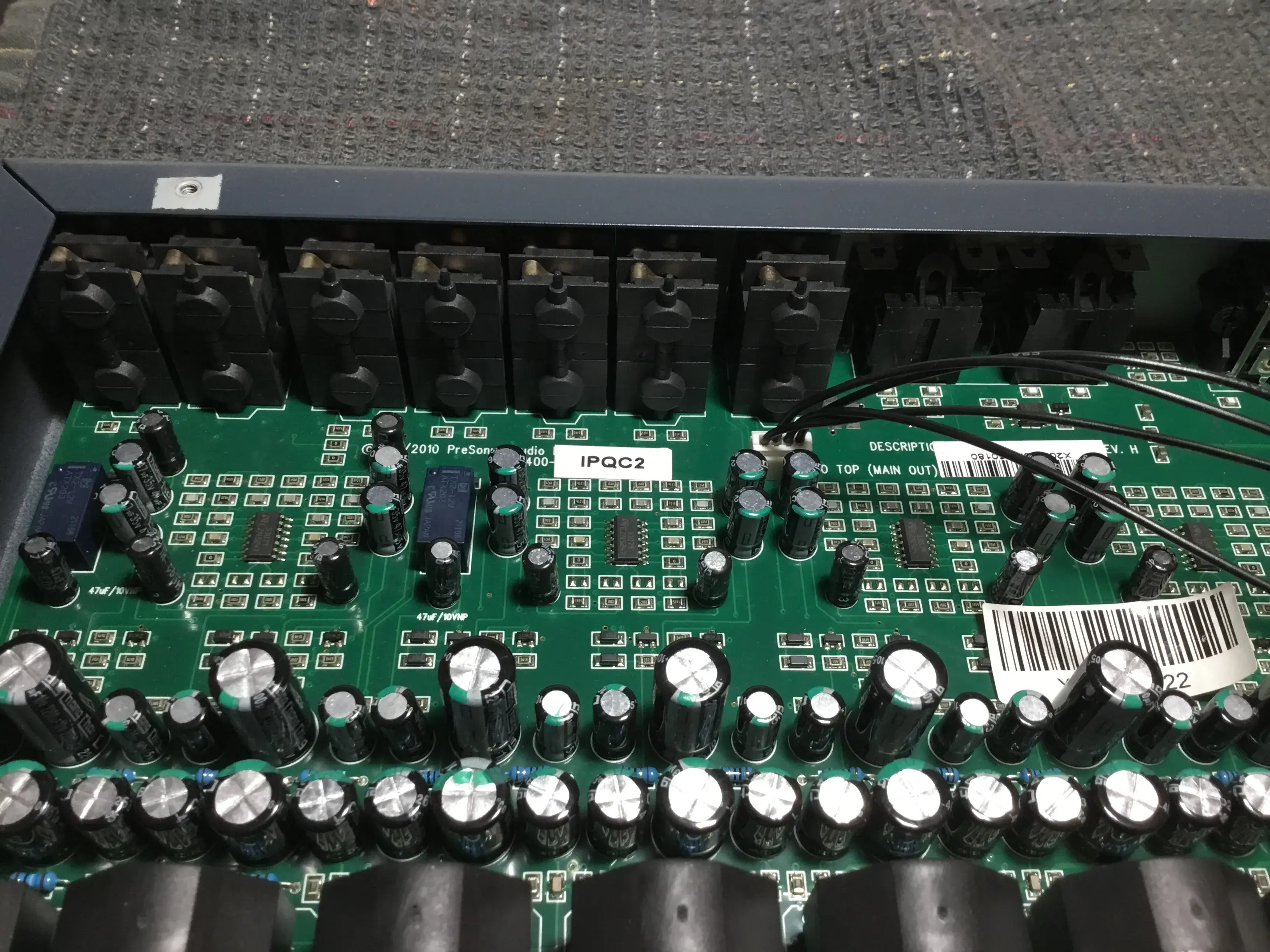
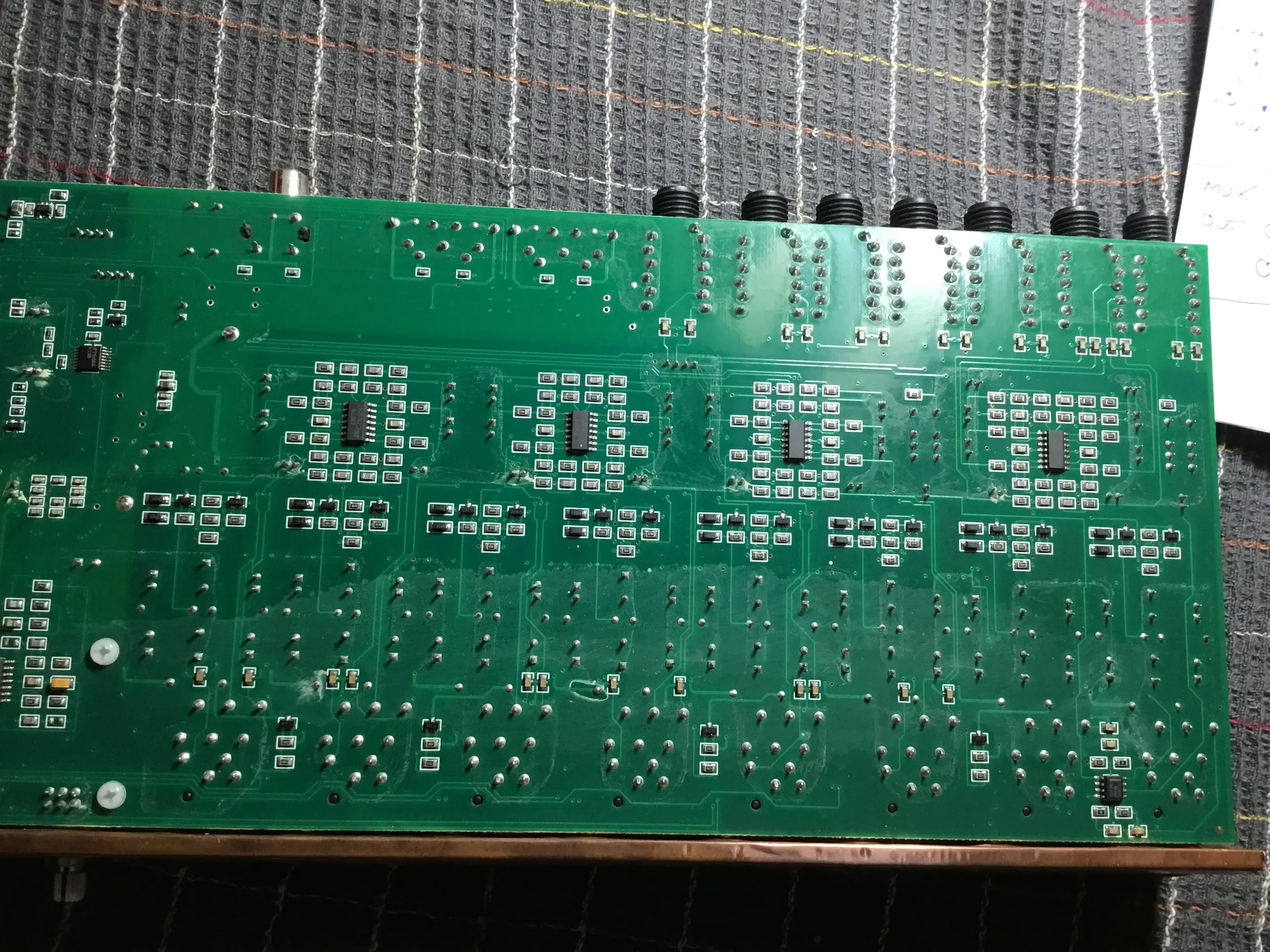
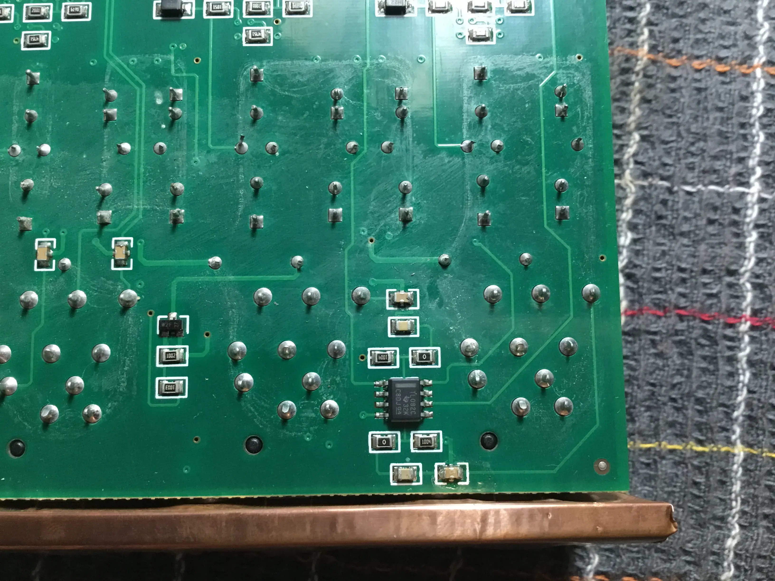
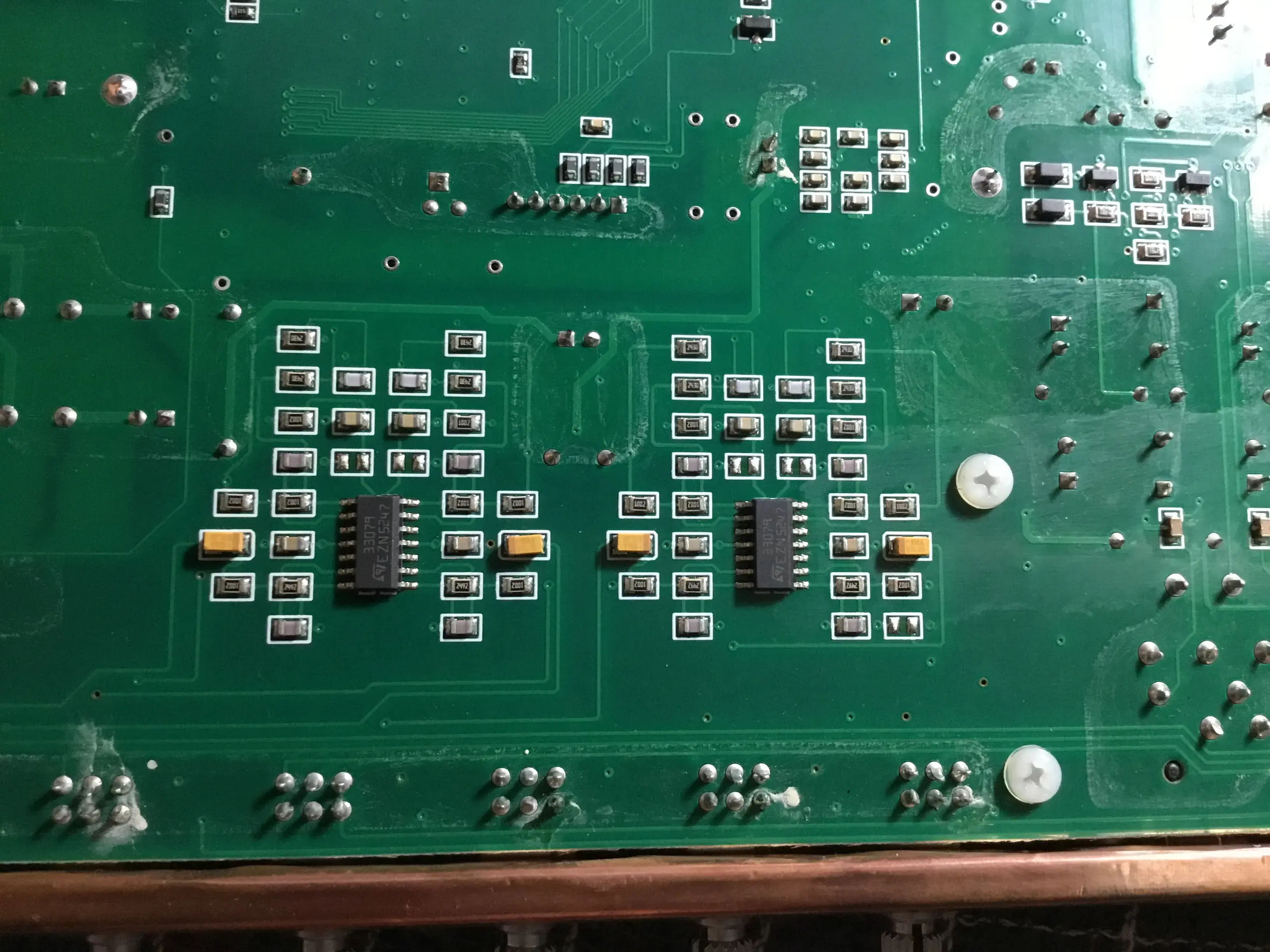
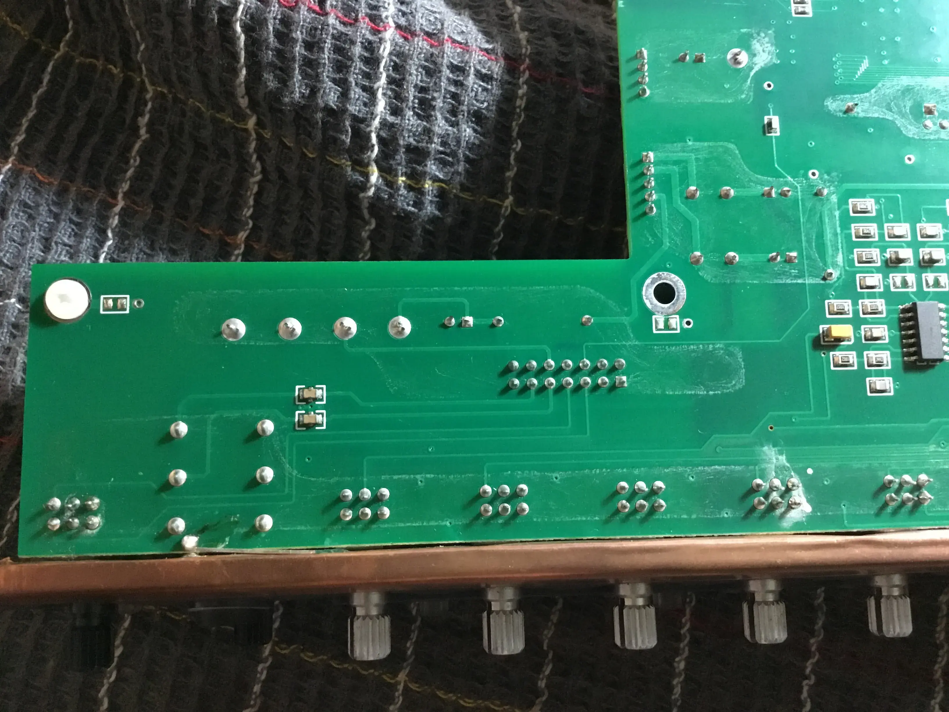
Photos of its internals (without fuegocable mod)
PCB version H (labeled as Rev. H)
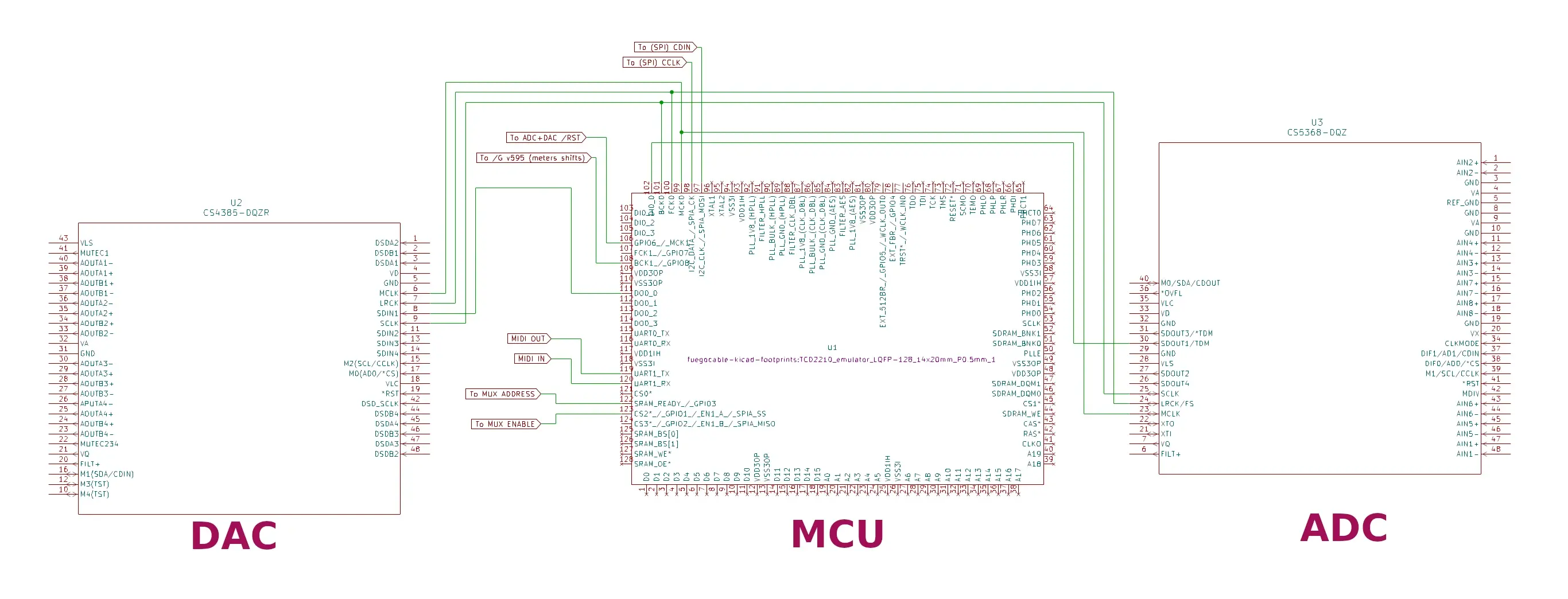
Reverse engineered circuit schematic
An incomplete schematic outline, yet useful for understanding some signals related to the TCD2210 main MCU. You can download the Kicad project (schematic plus some symbols) from this link.